A few weeks back, YouTube, in its desperate attempt to find something new and exciting to sate my lust for entertainment, started recommending video reviews of cheap knock-off pedals available through Temu. That whole Temu/AliExpress experience of buying the cheapest stuff imaginable from dodgy, faceless online retailers is not generally my vibe, so I was pleasantly ignorant to the existence of these pedals. But… If your morals can’t be flexible for gear acquisition, when can they be flexible?
The selection seemed impressive, and the price point was embarrassingly low, so I opted to pick up a few: Digital Delay, Analog Delay, Analog Chorus, Classic Chorus and Tremolo. They all have true bypass and sounded surprisingly not-craplike during my initial testing. So, what’s a DIY tinkerer to do, but tear them open and see what we can see?
Initial Findings
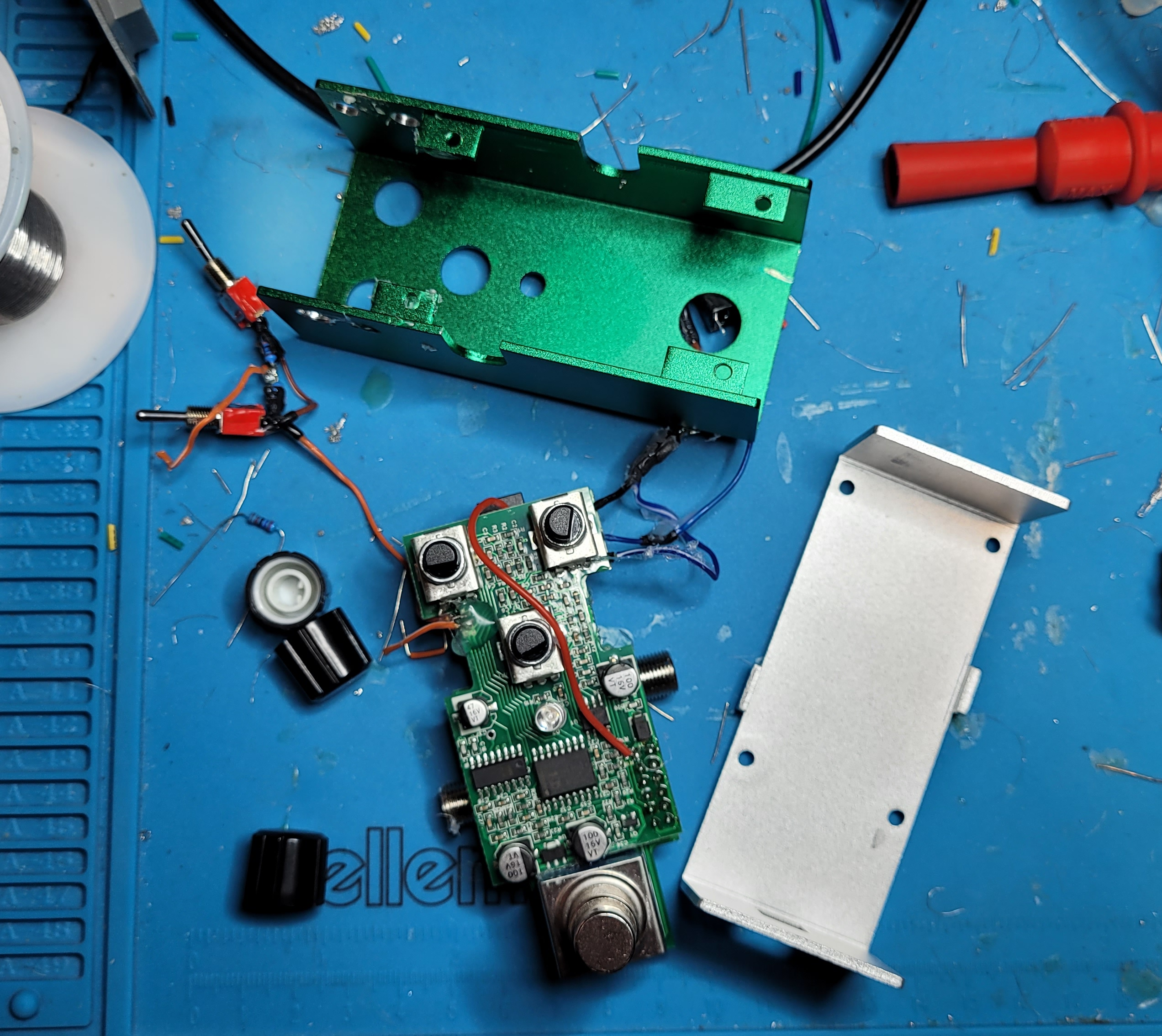
The chorus and delay pedals were all housed in a compact, sturdy aluminum case with rugged footswitches. They look and feel like they would hold up to the rigors of live performance. The tremolo is in a much less sturdy plastic case that inspired less confidence in its longevity. Inside, they’re all SMD reproductions of what appear to be relatively common circuits. Interestingly, but perhaps not shockingly, the Analog Delay and Digital Delay are the exact same circuit (CD2399-based delay); the Analog Chorus and Classic Chorus are also the same circuit (BBD chip based). It’s possible that “analog” and “digital” have different definitions in Temuland, but more likely they’re just trying to maximize sales and minimize production costs by selling rebranded effects to hapless and underfunded musicians. Capitalism.
Approach
Since these are such compact pedals, I wanted to try to retain that form factor. SMD circuits are also really finnicky and tedious to circuit bend, so I was looking for ways to dramatically change the effect the pedal produced, without adding so many components that it required a breakout box. Ultimately, I settled on finding 2-3 modifications per pedal–with a focus on making the most out of the fewest number of alterations.
Analog and Classic Chorus
Analog Chorus was the first pedal I popped open. Having just wrapped up the SoundTank CS5 bending project, my head was full of clock-modification bias, so that’s where I started. Like the CS5, these chorus pedals use a classic BBD chip and dedicated CMOS clock chip–in this case, the CoolAudio reproductions V3207 and V3102, respectively. If you’ve been following along with my pedal bends, you probably know where this is going…
Clock Modification
The clock rate of the V3102 is controlled by a combination of a capacitor (C25) and resistor (R43). The capacitor does most of the heavy lifting in this relationship (get your act together, resistor).
You’ll get the most response from swapping out the factory capacitor with one of a larger value. This will slow down the clock rate, pushing the chorus into lo-fi chaos territory. To the best of my reckoning, the factory capacitor is roughly 47pf. There are no markings on the capacitor and the little bugger is too small to get my multimeter leads on, but this seemed to be the closest match to the original effect.
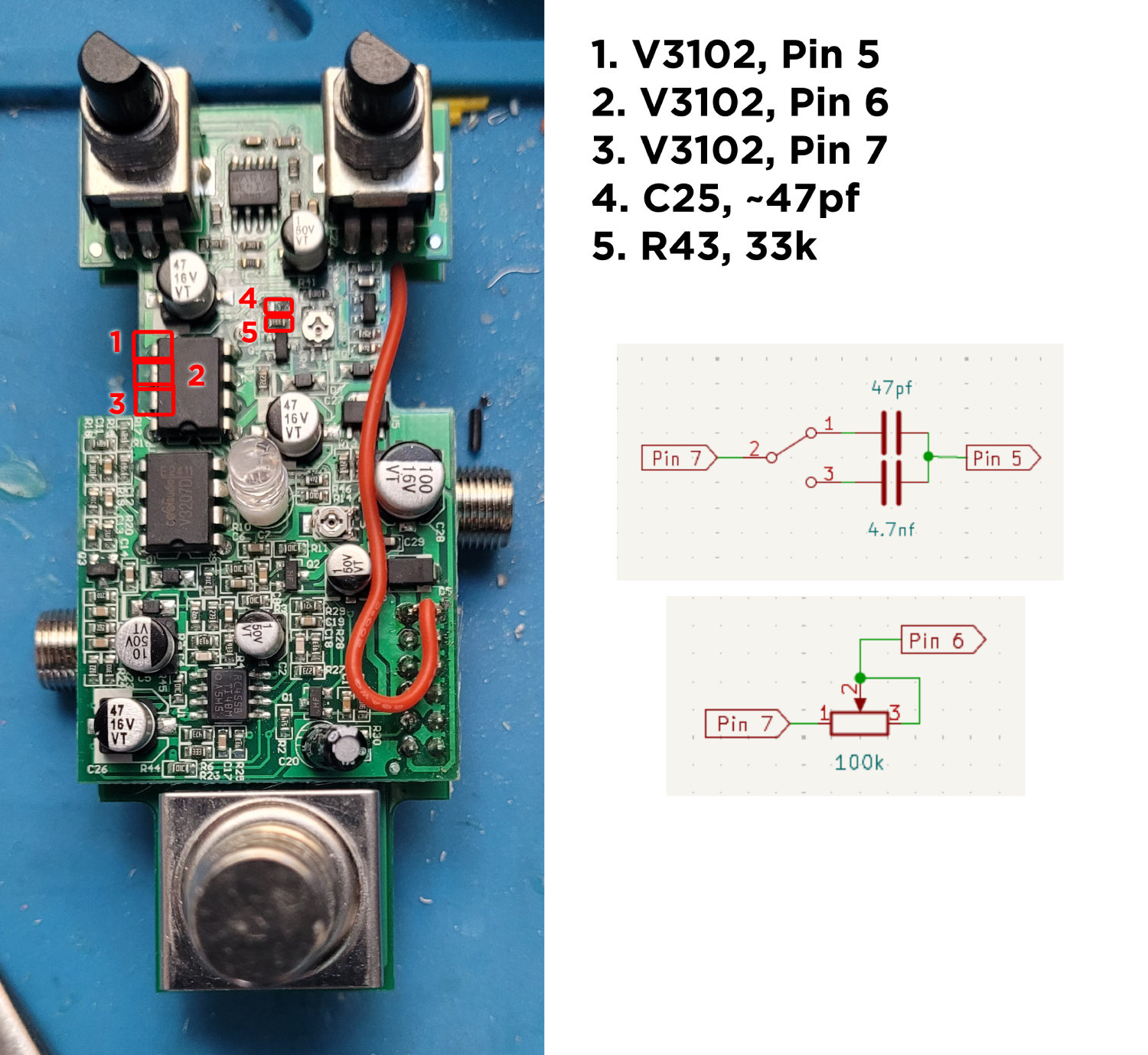
For the capacitor portion of the modification, I removed the factory capacitor (C25) and replaced it with an SPDT (On-On) switch. The center leg of the switch is wired to pin 7 of the V3102 chip. One side of the switch is wired to a 47pf capacitor, for normal operation. The other side of the switch is wired to a 4.7nf capacitor, for chaotic operation. The other ends of these capacitors are then wired together and connected to pin 5 of the V3102 chip.
The resistor isn’t completely worthless in this arrangement, so I replaced that as well. R43 is a fixed 33k resistor. I removed that and replaced it with a 100k potentiometer. Leg 2 of the potentiometer (middle leg) is connected to pin 6 of the V3102 chip. Leg 1 (left leg, as viewed from the top) is connected to pin 7 of the V3102 chip. This doesn’t do much when in normal mode. Depending on the dynamics of the pedal input, the sound gets close to breaking up, when the pot is at maximum. In chaotic mode, the pot has a more pronounced effect, subtly changing the nature of the Clocktastrophe™.
Analog and Digital Delay
Both of these delay circuits are built around an SMD version of the PT2399 chip. This is a digital delay chip, but the signal path in and out of the chip appears to be mostly analog. This might be how they justify calling it both a digital delay and an analog delay. Whatever their reasoning, it means that the same modifications can apply to both pedals. So, it all comes down to aesthetic choice: Which color pedal do you prefer?
VCO Rate Modification
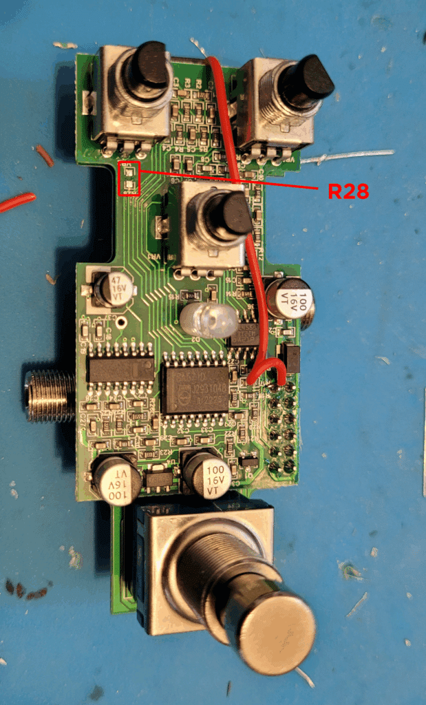
Pin 6 of the 2399 uses external resistors to set the rate of an internal VCO, which acts as the clock timer for the effect. This is accomplished by routing the signal first through a low-value, fixed resistor, and then into a higher-value potentiometer. In this case, that fixed resistor (R28) is 1k and the potentiometer is 50k.
The goal was to replace the fixed resistor with some different options, to have selectable delay ranges from slapback to chaotic degradation. (Sound degradation, not moral degradation. That’s a different project.) After some tinkering, I settled on three fixed values: 1k, to retain the original range; 51k, for a mostly useable long delay range; 100k, useless for delay, but amazing for chaotic effects.
Biggest hurdle: Finding a three-position rotary switch small enough to fit in the enclosure. After searching my usual haunts, then widening the net and coming up with nothing, I opted for an admittedly lame workaround: Daisy-chaining SPDT switches…
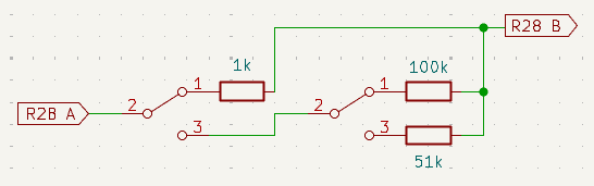
After removing R28, pick one of the solder pads (doesn’t matter which one) and connect that to the middle pin of the switch. One of the outside pins gets connected to a 1k resistor. The other outside pin gets connected to the middle pin of the second switch. The outside pins of the second switch are connected to a 100k resistor and a 51k resistor. The other ends of all three resistors are connected together, then to the other R28 solder pad.
When the first switch is in one position, it connects through the 1k resistor, which is the normal operating mode. When it is in the other position, it connects through the second switch (and whatever position that switch is in). When the second switch is in one position, it connects through the 51k resistor; in the other position, it connects through the 100k. It’s not an elegant solution, but it does allow for switching between all three ranges.
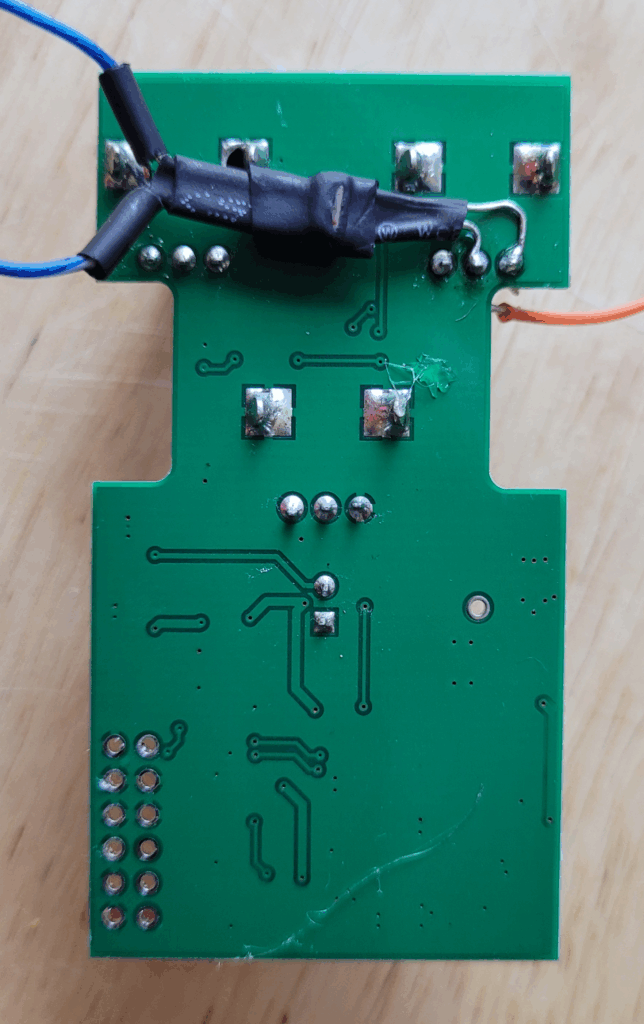
Pro Tip: If you accidentally destroy the R28 solder pads (it’s not difficult to do), you can (carefully!) wire the switches directly to the middle leg of the Time potentiometer and pin 6 of the 2399 chip–the smaller chip on the left side of the board. Locate the corner of the chip that has the pip, or dot, or divot. This is pin 1. The rest of the pins are numbered counter/anti-clockwise. So, in the picture above, pin 6 is the third from the left, on the top.
CV Control Delay Time
Want even more chaos? Add CV control over the delay time. This is a relatively simple modification, but it was complicated by my approach and dedication to maintaining the original form factor. To get everything crammed into the factory housing, I found that it was necessary to install the vactrol between the two PCBs. In order to do this, I had to desolder the header pins that connect the boards.
There are only three things you need for this modification:
- A vactrol (Here’s an excellent tutorial for making your own)
- A low-value resistor (1k should be fine)
- An input jack
A standard vactrol will have four leads, two sticking out of each side. There should be one side with two leads of the same length. This is the LDR (light-dependent resistor) side. These should be wired to legs 1 and 2 of the Time potentiometer (the left and middle legs, if viewed from the top). The other side of the vactrol should have leads of different lengths. This is the LED side. The longer lead is the anode–connect this to the CV input jack. The shorter lead is the cathode–connect this to ground, through the 1k resistor. Conveniently, the power jack is just below the pots, so you can tap into ground there.
Plug in an external voltage source (from, say, the LFO of a modular synth) and enjoy the chaos.
External Feedback Loop
Something I’d like to explore for future versions of this modification is an external feedback loop. This would pick up the feedback path somewhere between the output and where it feeds back into the input, and send it through an external loop. When nothing is plugged in, feedback would work as normal. Plugging a pedal into the loop would affect only the feedback iterations. Hopefully. We’ll see.
Tremolo
The tremolo is a common op-amp and vactrol circuit, where some of the op-amps are configured to produce an LFO and the LFO feeds into the vactrol, which modulates the input signal to produce the effect. The pedal I received was faulty and I did some initial exploration (seems to be a dodgy op amp at the summing stage), but ultimately put it on a shelf to revisit when I feel like troubleshooting the fault. My initial explorations were around modifying the LFO to change the frequency range. I was hoping to push the oscillator up into audio ranges to produce some AM effects. This can be done by adjusting the capacitor value (lower value = faster oscillation) of C5.
Leave a Reply