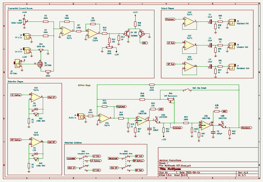
Multipass is a state-variable/multimode VCF, with some punch. Borrowing heavily from a design by Skull & Circuits, Multipass is an OTA-based filter with simultaneous highpass, lowpass and bandpass outputs.
I’ve leveraged some leftover op amps on the second TL074 to create switchable distortion stages for the lowpass and bandpass filters and added a gate switch for the second CV input. This allows for switching the second CV input on and off. And because I like it when things get real dirty, I added a secondary feedback path for the resonance.
Schematic
As with any schematic found on the internet, exercise caution when building. Test the build before plugging it into your case. If you find mistakes in the schematic, or you have recommendations for improving the design, feel free to contact me and let me know.
BOM
- Capacitors
- 22pf (2) C1, C5
- 10uf electrolytic (3) C2, C3, C4
- Resistors
- 1k (13) R1, R2, R13, R15, R17, R23, R24, R25, R26, R27, R29, R30, R31
- 10k (4) R12, R16, R20, R28
- 47k (1) R10
- 68k (2) R21, R32
- 100k (10) R3, R4, R5, R6, R7, R8, R9, R11, R18, R19
- 200k (2) R14, R22
- Potentiometers
- 100k (4) RV1, RV2, RV3, RV4
- 100k trim pot (1) RV5
- 1M (1) RV6
- Transistors
- 2N7000 (1) Q1
- 2N3906 (2) Q2, Q3
- ICs
- LM13700 (1) U3
- TL074 (2) U1, U2
- Switches
- SPST (1) SW3
- DPDT (2) SW1, SW2
- LEDs (2) D1, D2
- Audio Jacks (6) J2, J3, J4, J5, J6, J7
- Switched audio jack (1) J1
Design Notes
I did run into some issues with the highpass filter. The circuit is designed such that the highpass filter is derived from inverting the signal from the lowpass filter. However, the resonance is also derived from feeding the lowpass filter output back to the input stage. When the resonance is turned up, lower frequencies are not phase cancelled when inverted, so the highpass isn’t very … highpassy. Works just fine when the resonance is turned down, though. If you can figure out what I did wrong, let me know in the comments!
Demo
Coming soon
Did you build this? Let us know in the comments below!
2 responses to “Multipass”
-
Hi there! The schematic for this one is a PNG file and a little bit difficult to make out. Any chance for a pdf? Thanks for sharing all these – great to find some interesting wonky modules different from the norm!
-
Hello! Thanks for catching this. I’ve fixed the link and it should now point to the PDF instead of the PNG.
-
Leave a Reply