
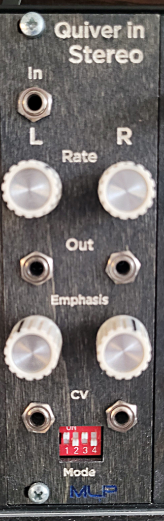
Another stereoizing effect, Quiver in Stereo splits a mono signal into two channels. Each channel has an independent LFO-driven tremolo that dictates the rate of “quiver” for that channel. Each channel also has a diode-clipping feedback path to add emphasis to the quivering effect. CV control over the feedback amount allows for even more stereo modulation.
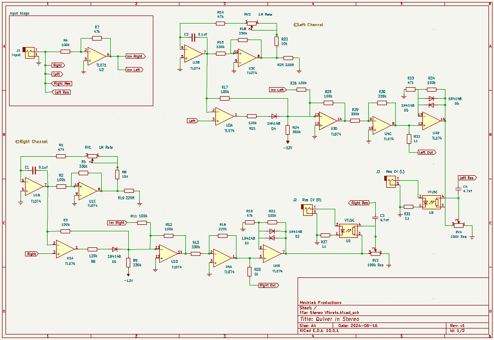
Schematic
As with any schematic found on the internet, exercise caution when building. Test the build before plugging it into your case. If you find mistakes in the schematic, or you have recommendations for improving the design, feel free to contact me and let me know.
BOM
- Capacitors
- 100nf/0.1uf (2) – C1, C2
- 4.7nf (2) – C3, C4
- Resistors
- 220R (2) – R10, R25
- 1k (4) – R20, R27, R31, R32
- 10k (2) – R8, R23
- 47k (5) – R1, R7, R14, R19, R33
- 100k (11) – R2, R3, R4, R11, R12, R15, R17, R22, R26, R28, R34
- 120k (2) – R6, R21
- 220k (2) – R16, R30
- 330k (6) – R5, R9, R13, R18, R24, R29
- Potentiometers
- 100k (2) – RV3, RV4 (Resonance)
- 1M (2) – RV1, RV2 (Rate)
- ICs
- TL071 (1) – U2
- TL074 (3) – U1, U3, U4
- Diodes
- 1N4148 (6) – D1, D2, D3, D4, D5, D6
- Audio jacks (5) – J1, J2, J3, J4, J5
- Vactrols (2) – U5, U6
Design Notes
Like Stereo Animator, this module is several years old and, until now, unshared with the world. I do seem to remember struggling to get this working correctly after it was built, so my lack of confidence in the design is likely the reason I hadn’t shared it. Lately, it’s showed up in a couple of tracks I’m working on, so it seems to be working well enough to put out there.
Maybe you can improve on the design and make it a little more predictable and a little less prone to bouts of pickiness.
Okay, so the input signal first gets split three ways: one each to the left and right channels, the last goes through an inverting op amp that reduces its volume by half. The uninverted (verted?) signals route through identical left and right paths, starting at an op amp. This op amp is configured as a noninverting op amp, where the input resistor is replaced with an LFO. If I’m understanding my own circuit correctly, this would modulate the amount of current dumped to ground, which would affect the amplification resistor ratio, causing the volume to modulate at the speed of the LFO.
This is summed with the inverted signal from the input, through an inverting op amp. This is then inverted again, to get back to the original polarity for output.
Moving past the output jack, there’s another op amp with opposing diodes in the feedback path. These provide non-linear soft clipping that gives the feedback signal some bite. Finally, there’s an input and vactrol for CV control over the feedback/resonance amount.
Uh. What about that switch?
One thing that’s not on the schematic, but is in the build, is the DIP switch. I think I ordered a handful of these by accident and was looking for a practical use for them. Here I’m using them to switch between LFO rate modes. I’ve supplemented C1 and C2 with an additional capacitor, each channel, and wired each of the four capacitors to one of the DIP switches. This allows me to set a faster or slower LFO rate, per channel.
It’s completely unnecessary. I’ve found that pushing the LFO up into audio range makes the effect nearly inaudible. Rather than getting a weird FM sound, it doesn’t sound like much of anything. Honestly, I left it out of the schematic for a reason.
Demo
Coming soon
Leave a Reply