
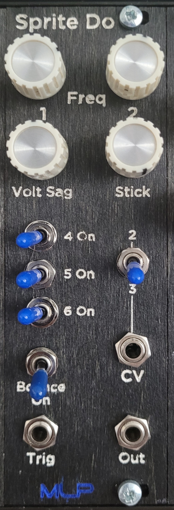
Sprite Do is a percussion module, designed to sound not at all like a drum. Maximizing the oscillator potential of the CD40106 chip, the stacked oscillators produce a wide range of purely electronic blips, bloops and boings that sound a lot like sprites* do.
Sprite Do has two always-on oscillators with variable frequencies and four optional fixed-frequency oscillators. Additionally there are rudimentary stick (or snap) and bounce (or pitch sweep) features, as well as a voltage sag for creating even weirder sounds.
*Sprites, in this context, are the graphic representations of characters in video games. Specifically, for the purposes of this play on words, the characters in old 8-bit video games.
Schematic
As with any schematic found on the internet, exercise caution when building. Test the build before plugging it into your case. If you find mistakes in the schematic, or you have recommendations for improving the design, feel free to contact me and let me know.
BOM
- Capacitors
- 3.9nf (2) – C5*, C7*
- 15nf (1) – C3
- 22nf (1) – C4
- 47nf (1) – C2
- 100nf (1) – C6*
- 1uf (1) – C1
- Resistors
- 200R (2) – R3, R12
- 1k (4) – R1, R2, R7, R13
- 6.8k (2) – R9, R11
- 51k (1) – R16*
- 56k (3) – R6, R8, R10
- 62k (1) – R15*
- 100k (2) – R4, R5
- 3M (1) – R14*
- Potentiometers
- 1k (1) – RV1
- 50k (1) – RV3
- 100k (2) – RV2, RV4
- ICs
- CD40106 (1) – U1
- TL071 (1) – U2
- Diodes
- 1N4148 (8) – D1, D2, D3, D4, D5, D6, D7, D8
- Audio jacks (3) – J1, J2, J3
- Vactrol (2) – U3, U4
- SPST switch (4) – SW1, SW3, SW4, SW5
- SPDT switch (1) – SW2*
*See Design Notes below
Design Notes
I’ve been trying to remember why I built this. I think it might have been a circuit design challenge from Moritz Klein, but I can’t find any supporting evidence for this thought.
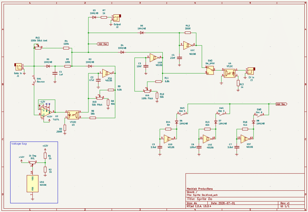
The core of this module is the CD40106 Schmitt-Trigger inverter chip. This chip is all over the place in DIY VCO schematics and tutorials (it’s the basis for my Chainsaw module, as well), and produces a very serviceable sawtooth oscillation. Here a gate or trigger impulse and some diodes are triggering a short oscillator burst to replicate a percussion sound.
I’ve added a few of my own elements to the core, which are neat, but certainly not necessary.
Stick and Bounce
I’d like to take a moment to appreciate the persnickety minds who initially approached electronic drums and rightfully pointed out how flat they sound. I would likely have never considered either the stick or the bounce, and lived out my days happy with flat electronic drums.
What I’m calling “stick” is conceptually inspired by Thomas Henry’s “impact tone generator”. It’s purpose is to add a transient snap at the beginning of the drum sound, to replicate the sound of a stick hitting the drum head (as opposed to the resonance of the drum as the hit reverberates). It’s a really, really simplified implementation that isn’t always immediately discernable in the final sound. But, when you hear it, it does make a difference in the snap of the drum.
What I’m calling “bounce” is the short pitch change that happens when the stick hits the drum head, deforming and stretching the head. I’m sure there are more elegant ways to implement this, but I chose the simple option of using a vactrol to add more resistance into the pitch stage of the first oscillator. The 56k and 200R resistors limit the intensity of the effect, so it doesn’t sound like a laser.
(Though, now that I’ve typed that, the thought has manifested in my brain. You might be able to have switchable resistors in parallel, to change the intensity of the effect, if you wanted lasers…)
Waste Not, Want Not
I am a frugal person–by nurture, not nature–so the idea of using only one of the six Schmitt-Triggers in the 40106 seemed wasteful to me. (This aversion of waste is what inspired the Chainsaw module linked above.) My obvious first thought was “if one oscillator is good for making a drum sound, stacked oscillators would clearly be better!”
Oscillator 1 is the core of the module. This is where most of the magic happens, and realistically you could create a functional drum out of just this. Oscillator 2 is a very similar design, without the bells and whistles (i.e., Stick and Bounce). Oscillators 3, 4, 5 and 6 are essentially the same, but at a fixed rate of oscillation. R14, R15 and R16, with C5, C6 and C7 control the rate of oscillation. I’ve chosen values that appeal to me, but you are encouraged to try different values to see what works best for you.
I’ve used switches to connect/disconnect these fixed rate oscillators to the main circuit. It would be possible (theoretically–I didn’t test this) to use potentiometers to control the level of each fixed rate oscillator in the final output. It would likely require using inverting unity gain op amps prior to the pot, then another inverting op amp to sum all the oscillators (including the variable rate ones). This would add a lot of complexity to the circuit, but might result in a more flexible drum sound.
CV Input
Nothing special happening here. Using a vactrol to provide voltage control over the rate of Oscillator 2 or Oscillator 3, switchable with a SPDT toggle.
I did opt for a center-off switch here. Oscillator 3 is designed as a fixed rate oscillator, where the resistor to ground is replaced with the vactrol. When no signal is present at the CV input, the vactrol resistance is extremely high, which results in oscillations outside audio range. This isn’t inherently bad, but the signal eats up headroom the audible oscillators need, without adding any value. Using a center-off switch allows me to disconnect the oscillator from the output, without needing a dedicated SPST switch for it.
Voltage Sag
This is some good, old-fashioned power starving. One of my favorite tricks from the world of circuit bending, the voltage sag can introduce a variety of different effects into some circuits. In this application, it affects the overall pitch of all the oscillators. Depending on the relationship of the pitch between the oscillators, this can produce some near-FM/near-8 bit sounds.
One side of the potentiometer has two 1k resistors configured as a voltage divider. This is reducing the voltage by half, bringing the +12V down to +6V. This feature will work on voltages over than +12V, but might require some adjustments. The minimum recommended operating voltage of the CD40106 is +3V, so the voltage divider shouldn’t result in anything lower than that.
Demo
Coming soon
Leave a Reply