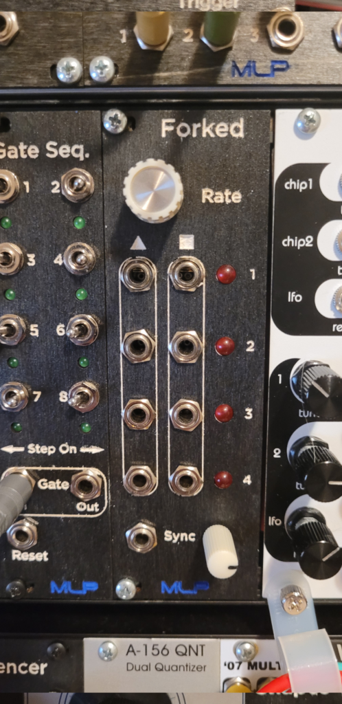
Conceptually based on the DivKid/Instruo Ochd (but with four LFOs instead of eight–get it?), Forked is a free-roaming modulation workhorse, with triangle and square outputs. One rate knob sets the general speed for each LFO, all of which run independently and asynchronously from one another.
Triangle out provides ample modulation opportunities, while square out can act as a gate signal for self-patching or triggering other modules. Patch a clock into the hard Sync input to reset each LFO in time with a gate pulse to create modulations that start in time with the clock … but don’t run in time with the clock.
It’s called Forked because it has four LFOs, but you can expand it to six for Sexed or 12 for Dodecahexed. You’re only limited by HP space and your patience.
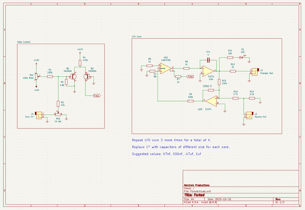
Schematic
As with any schematic found on the internet, exercise caution when building. Test the build before plugging it into your case. If you find mistakes in the schematic, or you have recommendations for improving the design, feel free to contact me and let me know.
BOM
Rate Control
- Resistors
- 1.8k (1) R3
- 47k (1) R2
- 100k (1) R1
- 470k (1) R4
- Potentiometers
- 100k (2) RV1, RV2
- Transistors
- 2N3906 (2) Q1, Q2
- Audio jacks (1) J1
LFO Core (Multiply quantity by total number of LFO cores desired)
- Resistors
- 1k (5) R5, R6, R7, R8, R12
- 2.2k (1) R14
- 2.7k (1) R13
- 10k (1) R11
- 100k (2) R9, R10
- 22ok (1) R — oops
- Capacitors
- Value varies (1) C1*
- ICs
- LM13700 (0.5) U1
- TL074 (0.5) U2
- Audio jacks (2) J2, J3
- LED (1) D1
*Choose a different value capacitor for each LFO core to achieve different LFO speeds. Individual tastes and preferences will vary. Recommendations include 47nf, 100nf, .47uf, 1uf
Demo
Coming in the future.
Did you build this? Let us know in the comments below!
2 responses to “Forked”
-
How is the LM13700 powered? +/-12v, +/-5v or +5v/Gnd? I don’t get it working. I have some trouble getting this Forked working. When powering with +/-12v it behaves nasty and not LFO like.
-
Hey there. I just pulled the module from my case and checked it against the schematic. It is powered +/-12v and the schematic matches what I built. In what way does it behave unlike an LFO? Something to keep in mind is that the LM13700 is a finnicky chip. It doesn’t take much current at the bias input (pins 1 and 16) to damage it. I’ve accidentally fry quite a few while making bonehead mistakes on the breadboard. If you’ve confirmed that your build matches the schematic, you might try swapping out the LM13700 to see if that makes any difference.
-
Leave a Reply