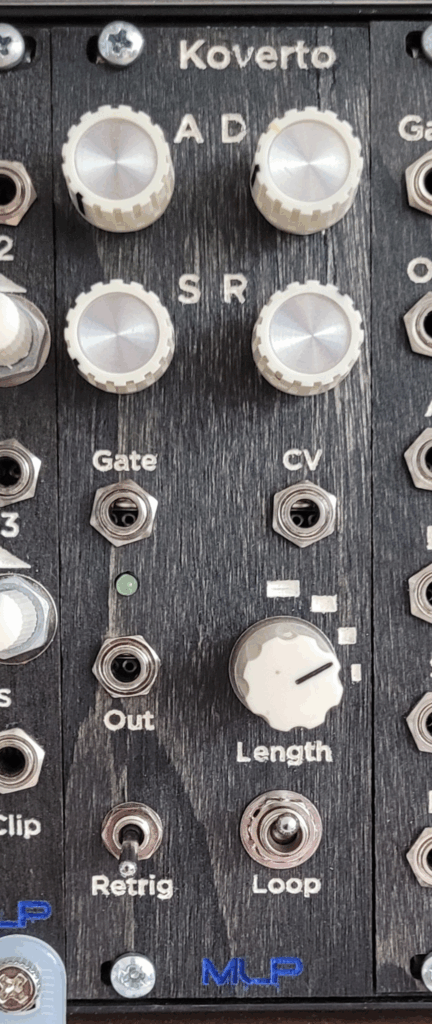
“Koverto” comes from the Esperanto word for “envelope”, and like Esperanto itself, Koverto takes inspiration from a variety of existing sources, and boils them all down into a single entity.
The basic structure leans heavily on the Analog Output precision ADSR, which, in turn, is derived from the Kassutronics precision ADSR, which, in turn, is derived from the Yusynth 555-based ADSR, which, in turn, is based on a Jonathan Jacky article from 1980–and is from the same family as Rene Schmitz’s “Fastest Envelope in the West”. All that to say, Koverto is standing on the shoulders of giants. And maybe not treading new ground.
Where Koverto diverges from these is in the implementation of an analog-switch-based retriggering feature and an additive CV input for mixing additional input sources post gate-to-trigger conversion.
In the former, the output envelope is used to activate the switch, sending another pulse to the input gate-to-trigger converter when the envelope finishes. The shorter the envelope, the more times it retriggers between gate pulses.
The latter offers the option to inject additional CV sources into the signal path, bypassing the input gate-to-trigger converter. For example, using an LFO to modulate the envelope or another gate/trigger signal to open the envelope at random times.
I’ve also implemented the looping feature from Analog Output and, just for kicks (and because I had one lying around), a rotary switch with four selectable envelope lengths. Short envelopes for super tight, plucky sounds. Longer envelopes for looser sounds and more flexibility with looping and retriggering.
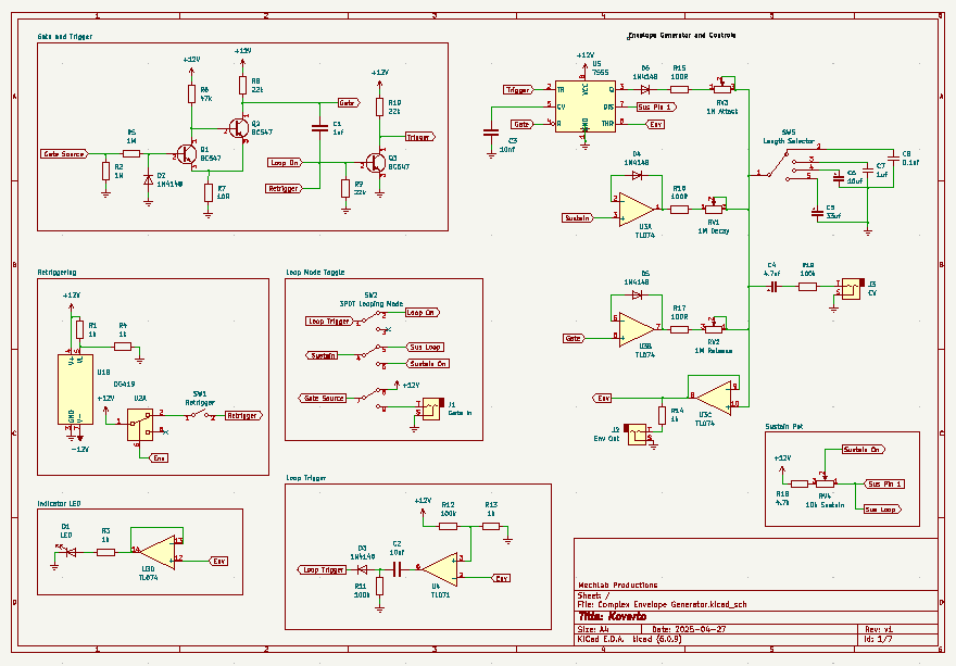
Schematic
As with any schematic found on the internet, exercise caution when building. Test the build before plugging it into your case. If you find mistakes in the schematic, or you have recommendations for improving the design, feel free to contact me and let me know.
BOM
- Capacitors
- 1nf (1) C1
- 10nf (2) C2, C3
- 100nf (1) C8
- 1uf (1) C7
- 4.7uf electrolytic (1) C4
- 10uf electrolytic (1) C6
- 33uf electrolytic (1) C5
- Resistors
- 10R (1) R7
- 100R (3) R15, R16, R17
- 1k (5) R1, R3, R4, R13, R14
- 4.7k (1) R18
- 22k (3) R8, R9, R10
- 47k (1) R6
- 100k (3) R11, R12, R19
- 1M (2) R2, R5
- Transistors
- BC547 (3) Q1, Q2, Q3
- Potentiometers
- 10k (1) RV4
- 1M (3) RV1, RV2, RV3
- ICs*
- DG419 (1) U1
- TL071 (1) U4
- TL074 (1) U3
- 7555 (1) U5
- 1N4148 diodes (5) D2, D3, D4, D5, D6
- LED (1) D1
- Audio jacks (3) J1, J2, J3
- SPST (1) SW1
- 3PDT (1) SW2**
- 4-pole rotary switch (1) SW5**
* There is no U2. It’s not personal…
** I couldn’t be bothered to dig up KiCad symbol libraries for these switches, so I cobbled together my own from what was available. The schematic should be clear, even if it’s not entirely standard.
Demo
Did you build this? Let us know in the comments below!