
Mabu-CA is an OTA-based VCA* with an integrated waveshaper. The waveshaper has two modes: Input and Follower. Input mode relies on an external control voltage to activate the MOSFET waveshaper. Follower mode uses the the CV envelope plugged into the VCA CV input, with an option to select between tapping into the raw CV (pre) or the biased CV (post) to control the waveshaper.
I’ve also included a summing output and individual level control over each channel, to allow sum mixing of all the inputs.
*If you can figure out the name of the module based on that description … your brain is also a very weird place.
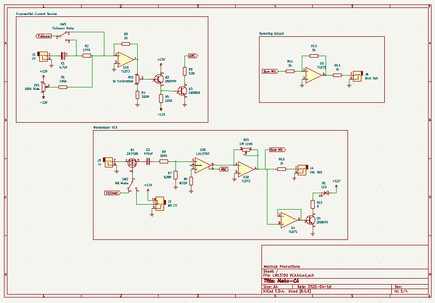
Schematic
As with any schematic found on the internet, exercise caution when building. Test the build before plugging it into your case. If you find mistakes in the schematic, or you have recommendations for improving the design, feel free to contact me and let me know.
BOM
- Capacitors
- 470nf (1) C2
- 4.7uf electrolytic (1) C1
- Resistors
- 390R (1) R4
- 620R (2) R7, R9
- 1k (4) R10, R11, R12, R13, R14
- 2k (1) R3
- 3.9k (1) R8
- 100k (4) R1, R2, R5, R6
- Transistors
- 2N3904 (2) Q2, Q4
- 2N3906 (1) Q3
- 2N7000 (1) Q1
- Potentiometers
- 1k trimmer (1) RV2
- 100k (1) RV1
- 1M (1) RV3
- ICs
- TL071 (2) U4, U5
- TL072 (1) U1/ U3
- LM13700 (1) U2
- SPDT switch (2) SW1, SW2
- LED (1) D1
- Audio jacks (4) J1, J2, J4, J5
- Switched audio jack (1) J3
Design Notes
When I was designing this, I imagined that having an exponential current source would open up some interesting possibilities for the control voltage. But, I haven’t really found that to be the case. At least not so far.
The complexity of the CV input could be greatly reduced in favor of a more straightforward linear CV, likely without sacrificing any of the useful functionality of the VCA. It’s something I will test eventually, but for now it works well enough for noodling.
Schematic Notes
- Schematic represents a single channel of the VCA.
- To combine multiple channels into a single module (as I’ve done in the demo picture), multiply everything in the Exponential Current Source and Waveshaper VCA boxes by the number of channels you want to include.
- Bear in mind that the LM13700 is a dual OTA, so you can use one chip for two channels.
- The Summing Output remains the same–connect Sum Mix from each channel to the Summing Output.
- Technically the op amp designated U3 can be the other side of U1. This doesn’t need to be a separate TL072.
- For that matter, all four of these op amps can be consolidated into a single TL074 for simplicity. If you’re adding multiple channels, just keep count of your op amps and use the package that makes the most sense for your build.
Demo
Did you build this? Let us know in the comments below!
Leave a Reply