Something my case has been sorely missing is a full-featured, syncable LFO. I have a variety of LFOs, with each of them bringing one thing to the table, but lacking in something else. So, I set out to build an LFO from scratch that would be syncable and offer a variety of unipolar waveforms.
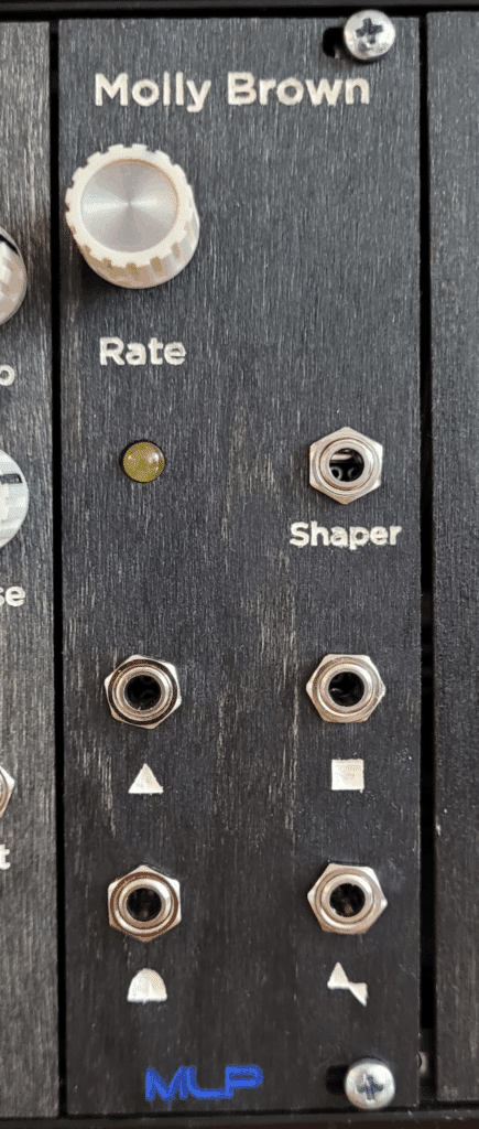
However, try as I might, I just couldn’t sync Molly Brown, so I settled for this free range LFO instead. It’s a triangle core oscillator, with various shaping functions to achieve simultaneous triangle, square, hump and serrated outputs. Additionally, there’s a 2N7000 based waveshaper to add CV-controllable weirdness to the output.
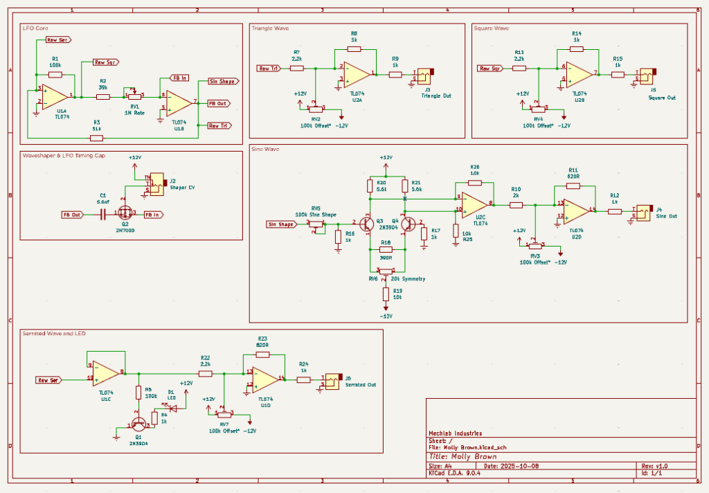
Schematic
As with any schematic found on the internet, exercise caution when building. Test the build before plugging it into your case. If you find mistakes in the schematic, or you have recommendations for improving the design, feel free to contact me and let me know.
BOM
- Capacitors
- 5.6uf (1) C1
- Resistors
- 390R (1) R18
- 620R (1) R11
- 820R (1) R23
- 1k (9) R4,R8,R9,R12,R14,R15,R16,R17,R24
- 2k (1) R10
- 2.2k (3) R7,R13,R22
- 5.6k (2) R20, R21
- 10k (3) R19,R25,R26
- 39k (1) R2
- 51k (1) R3
- 100k (2) R1, R5
- Potentiometers
- 1M (1) “Rate” RV1
- 20k trimmer (1) “Symmetry” RV6
- 100k trimmer (4) “Offset”, (1) “Sine Shape” RV2, RV3, RV4, RV7, RV5
- Transistors
- 2N3904 (3) Q1, Q3, Q4
- 2N7000 (1) Q2
- ICs
- TL074 (2) U1, U2
- LEDs (1) D1
- Audio jacks (5) J2, J3, J4, J5, J6
Design Notes
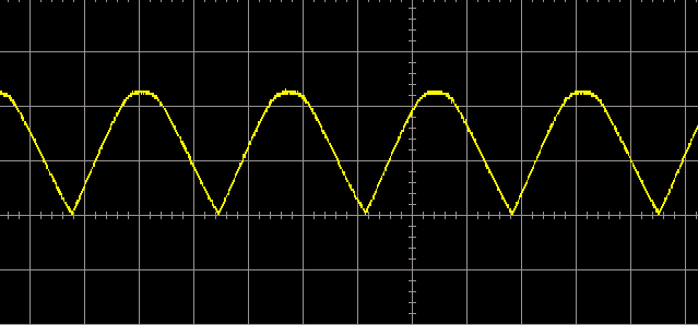
I’m calling this a “sine” in the schematic, but it’s actually more of a hump. The sine shaper circuit was cribbed from an old Thomas Henry book, and works great in some of my other oscillators. In this circuit, the bottom of the wave comes to a point, rather than a smoothly curved sinusoidal wave.
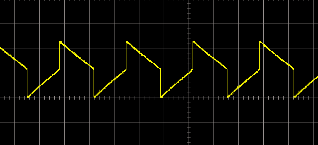
This was a weird, bonus waveform that I found hanging out on the LFO core. It’s a ramp wave, but instead of completing a smooth ramp down to 0 volts, it hits the midway point of the cycle and completely inverts, then starts to ramp back up to the midway point.
The raw signals out of the LFO core are hot and bipolar. I wanted to tone these down to a unipolar 5vpp signal. I made one design choice and one mistake that could be changed if you’re up for experimenting.
The design choice was to use trim pots instead of fixed resistors for the offset. This allowed me to dial in a precise offset to get the waveform starting at 0v (so I won’t get any zero-crossing clicks). Fixed resistors are cheaper, but I found that the necessary values were too wonky and too imprecise. You could do the math and save some money, if you’re not worried about it being exact.
The mistake comes in the scaling op amps. Specifically in the resistors used to scale the signal down in the final inverting op amp stage. I got all fancy and tried to use my new oscilloscope to visually confirm the voltage range. Unfortunately, I was reading it incorrectly and ended up building the module with the wrong resistors. Based on how the module was physically built, I was locked in to the 2.2k input resistor, so I could only adjust the feedback resistor. This limited my options, and I had to settle on waveforms that are ~4.6vpp, which is good enough for me. You can do the math and implement a better set of scaling resistors here to get more precision.
Demo
Coming soon
Did you build this? Let us know in the comments below!
Leave a Reply