Bending Guide
Using This Guide
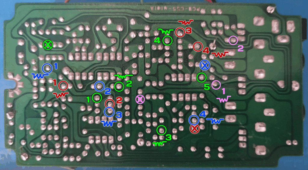
Bending Guides show specific bends that I have identified as interesting. Color-coded circles indicate separate bending points that all connect to a common point. I call this the Point of Origin (or POO) and indicate the POO with a circle marked with an “X”.
Occasionally a circle will be marked with a zigzag line . This means that I found it useful to add a potentiometer between this point and the POO. These are optional additions–the bend will function just fine with a normal switch.
Suggested Resistor Values
This is my most complex “additional components” build to date. Several of the bends work best (or, in the case of Red 1, at all) with a fixed-value resistor between the bending point and the POO. Some of the bends have combined fixed and variable (potentiometer) resistors.
- Blue 1 – 20k (fixed)
- Blue 3 – 100k (potentiometer)
- Blue 4 – 5k (potentiometer)
- Green 2 – 20k (fixed)
- Green 3 – 100k (fixed)
- Green 4 – 10k (fixed) -> 100k (potentiometer)*
- Pink 1 – 100k (potentiometer)
- Red 1 – 13k (fixed)**
- Red 3 – 10k (fixed) -> 20k (potentiometer)*
- Red 4 – 5k (potentiometer)
*For the fixed-to-potentiometer bends, I wired the fixed resistor directly to the leg of the potentiometer, then soldered the wire from the bending point to the other end of the resistor
**13k is not a common resistor value. I used a 1k resistor in series with a 12k resistor. You could also use a 20k trimmer pot to dial in the desired effect.
I appreciate that this is an obnoxious variety of potentiometer values, but these are the values I found gave me the best performance for each bend. If you don’t want to buy a bunch of new pots, just use what you have.
Additional Modifications
This modification is the real star of the project. I had a real “whoa” moment when I found it.
Clock Mod
Like many classic chorus designs, the CS5 is built around an old bucket-brigade delay (BBD) chip: the MN3207. The MN3200 series requires an external clock source, typically provided by the MN3102–a dedicated CMOS clock designed for the purpose.
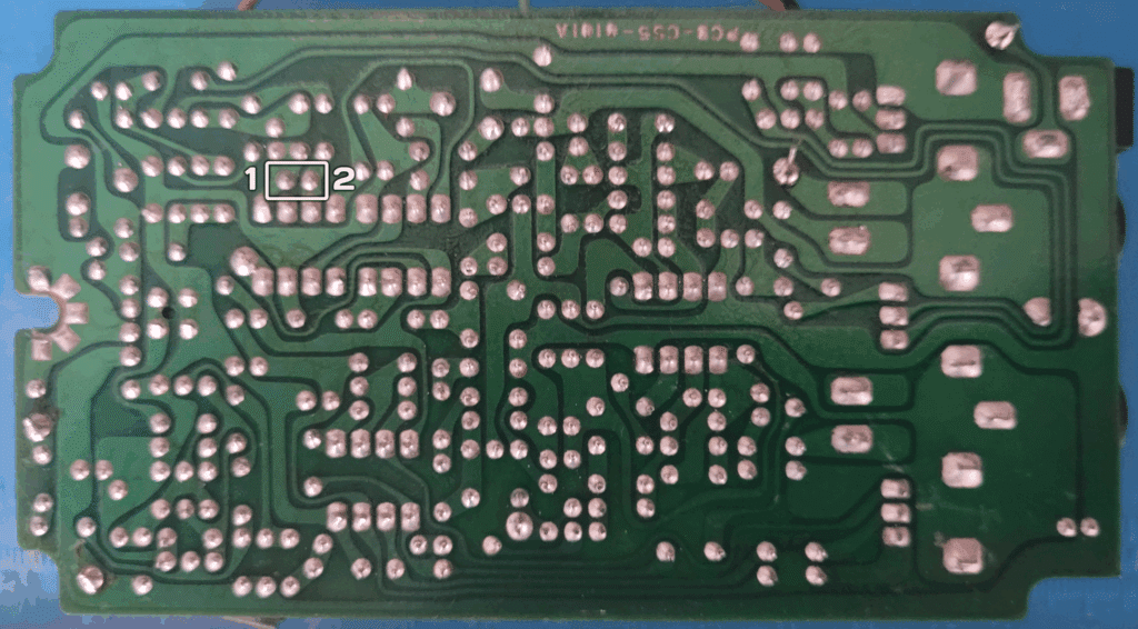
The clock rate of the MN3102 is determined by a capacitor/resistor pair. Adjusting the values of these two components changes the frequency range of the clock. Pins 1 and 2, above, are where the capacitor connects to the board.
I replaced the stock 10pf capacitor with a 3-way switch, allowing me to switch between 10pf (normal operation), 100pf (slow clock) and 1nf (glacially slow clock). The slower the clock speed, the more chaotic and lo-fi the sound becomes.
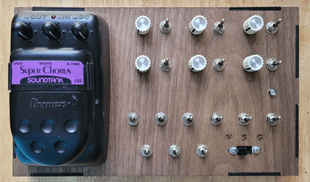
Built from: Ibanez SoundTank CS5 Super Chorus
Number of bends: 15
Description: Our first new pedal bend of the year!
The SoundTank line was Ibanez’s answer to the question “What would it look like to make a really cheap pedal that would appeal to gearlusting teenagers who can’t afford anything better?”
It’s no coincidence that the SoundTank Auto Wah was the first pedal I ever bent. This project was a bit like returning to my roots–only this time around it was intentional: I wasn’t bending the cheapest pedal I owned, for fear of ruining something of value.
The CS5 revealed a lot more than I expected. I settled on 15 different bends. Some are subtle shifts of the chorus effect; some are piercing electronic squeals; some overdrive; some intense modulation; some that really don’t shine until layered with other bends.
Pink 1 and Pink 2 are especially rewarding, with Pink 1 garnering an extremely rare (for me) LDR for performance bending. Coupled with the clock mod, it can create some really chaotic effects.
Demos
The following demos all feature a simple synth sequence running through the CBSC. Each demo starts with a clean signal, then the chorus is turned on, then the bend is connected. There is slight compression and limiting on the signal, but no additional effects.
Blue 1
Blue 2
Blue 3
Blue 4
Green 1
Green 2
Green 3
Green 4
Green 5
Pink 1
Pink 2
Red 1
Red 2
Red 3
Red 4
Clock Mod
Did you build this? Let us know in the comments below!
Leave a Reply