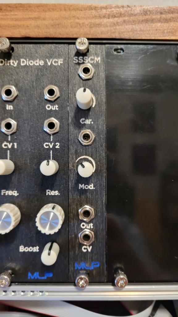
The next time someone tells you math isn’t magical, introduce them to the Single Sideband-Suppressing Carrier Modulator–or SSSCM for short. Based on 20th century broadcast technology, the SSSCM uses a modulator signal to suppress one sideband of the carrier signal, then adds the two together. The resulting audio has a wide range of modulation sound effects from pulse width modulation to ring modulation to frequency modulation.
CV control over the positive input bias allows for sweeping in the effect with an LFO, or using an envelope generator to create VCA-like amplification. This circuit is based on an MC1496N chip, but should work with other modulator/demodulator chips, such as the MC1596, LM1496 or LM1596. Pinouts might vary across these chips, so compare with the pinout of the MC1496 when wiring.
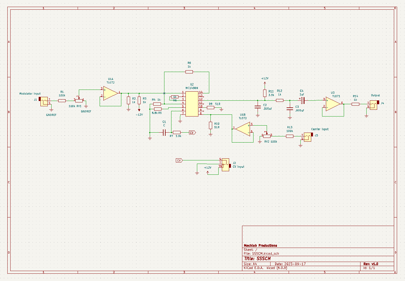
Schematic
As with any schematic found on the internet, exercise caution when building. Test the build before plugging it into your case. If you find mistakes in the schematic, or you have recommendations for improving the design, feel free to contact me and let me know.
BOM
- Resistors
- 51R (2) R9, R10
- 1k (7) R2, R3, R4, R6, R8, R12, R14
- 3.9k (2) R7, R11
- 6.8k (1) R5
- 100k (2) R1, R13
- Capacitors
- 0.005uf (3) C1, C2, C3
- 1uf electrolytic (1) C4
- Potentiometers
- 100k (2) RV1, RV2
- ICs
- TL071 (1) U3
- TL072 (1) U1
- MC1496N (1) U2*
- Audio jack (3) J1, J3, J4
- Switched audio jack (1) J2
* MC1596, LM1496 or LM1596 should work as well–compare the pinouts to ensure correct wiring
Demo
Did you build this? Let us know in the comments below!
Leave a Reply