Preamble
I have decided to try something different and offer some insight into how new designs come to fruition in the Mechlab. I will be dissecting our latest design, Rock Throbster, with the aim of demonstrating how each element of the design came together and how it can be modified to suit different needs. Lacking a background in electrical engineering (and being rubbish at math), I will be focusing on how different aspects of the circuit work, functionally, not theoretically.

In the two and a half years that I’ve been building my own Eurorack system, I’ve found a wealth of helpful resources, both online and in print. Some of these are written for enthusiasts and amateurs. But, many are written for people who understand the theory that underlies the design–and these almost always go straight over my head.
What I’ve longed for, and what I hope this post accomplishes, is a way to look at a schematic and understand what each part is doing, functionally, so that I know what parts I can remove because I don’t want them, or which parts I can modify to suit my tastes, or where I can add new things without breaking the core functionality.
I believe that there is a not-inconsequential element of the DIY aesthetic that relies on surprise and serendipity. That’s why we call it the Mechlab. It’s a place for experimentation. Sometimes it’s fun to stick a Bunsen burner under something and see what happens. But, sometimes it’s nice to have some guidance, so you don’t accidentally burn the place down.
Bit of History
Like many of our module designs, this one happened organically. After spending an afternoon assembling some homemade vactrols, to build a vactrol-based VCF, I found myself with a surplus that I was eager to use. Scouring the internet for ideas, I came upon some old schematics for the discontinued Tremulus Lune tremolo pedal. After breadboarding the circuit, I found myself uninspired by the results. The circuit was originally designed for a unipolar, 9v supply–I thought maybe I could OOMPH it up a bit by converting the circuit to bipolar 12v. This did improve the effect, but not by much. In the context of a modular synth, there was very little … pizzazz. Lots of knobs that didn’t seem to accomplish much and a weak overall depth to the effect.
Tremolo, as an effect, is essentially amplitude modulation. You’re using one signal to vary the amplitude (volume) of another to create a “trembling” sound, without affecting the frequency (pitch). Since there are countless ways to achieve amplitude modulation in a modular synth, there aren’t many modules dedicated to it as a sole function. Without much to go on for inspiration, and not wanting to completely abandon the idea, I decided to deconstruct the Tremulus Lune schematic, to the best of my abilities.
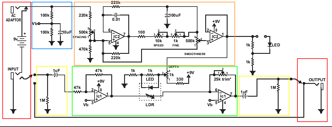
The parts in…
- Red I could confidently identify as the input, output and power supply. I knew I could disregard these, since they wouldn’t necessarily translate from a guitar pedal to a synth module.
- Blue are two resistors forming a voltage divider, and a capacitor for power supply conditioning. This creates a sort of virtual ground to force the op amp to behave as though it is running on a bipolar supply. The pins that would normally be grounded at 0v, are now grounded at 4.5v, which is halfway between 0v and 9v. Or something. Regardless, I knew I wouldn’t need it for a module with a bipolar supply.
- Orange had all the appearance of an LFO. Granted, not a design I’d seen before, but that section was powering the LED side of the vactrol. When the LFO signal is high, the light is on. When the LFO signal is low, the light is off. This causes the LDR to “open” and “close” the path through which the audio signal passes, creating amplitude modulation.
- Yellow provide AC coupling for the input and output signal, to remove any DC offset introduced to the audio. Not important for my application, so I knew I could get rid of those, as well.
- Green are my audio signal path. After passing through the AC coupling, the audio passes through an inverting buffer (signal is inverted, with a gain of 1). It passes through the LDR side of the vactrol and on to another inverting amplifier, configured with a trim pot in the feedback path. The trim pot either allows you to dial in a make-up gain (amplification level) that suits your tastes, or it allows you to dial in the necessary resistance to create a unity gain buffer with the input resistance from the LDR. I think. It’s kind of the same concept, either way.
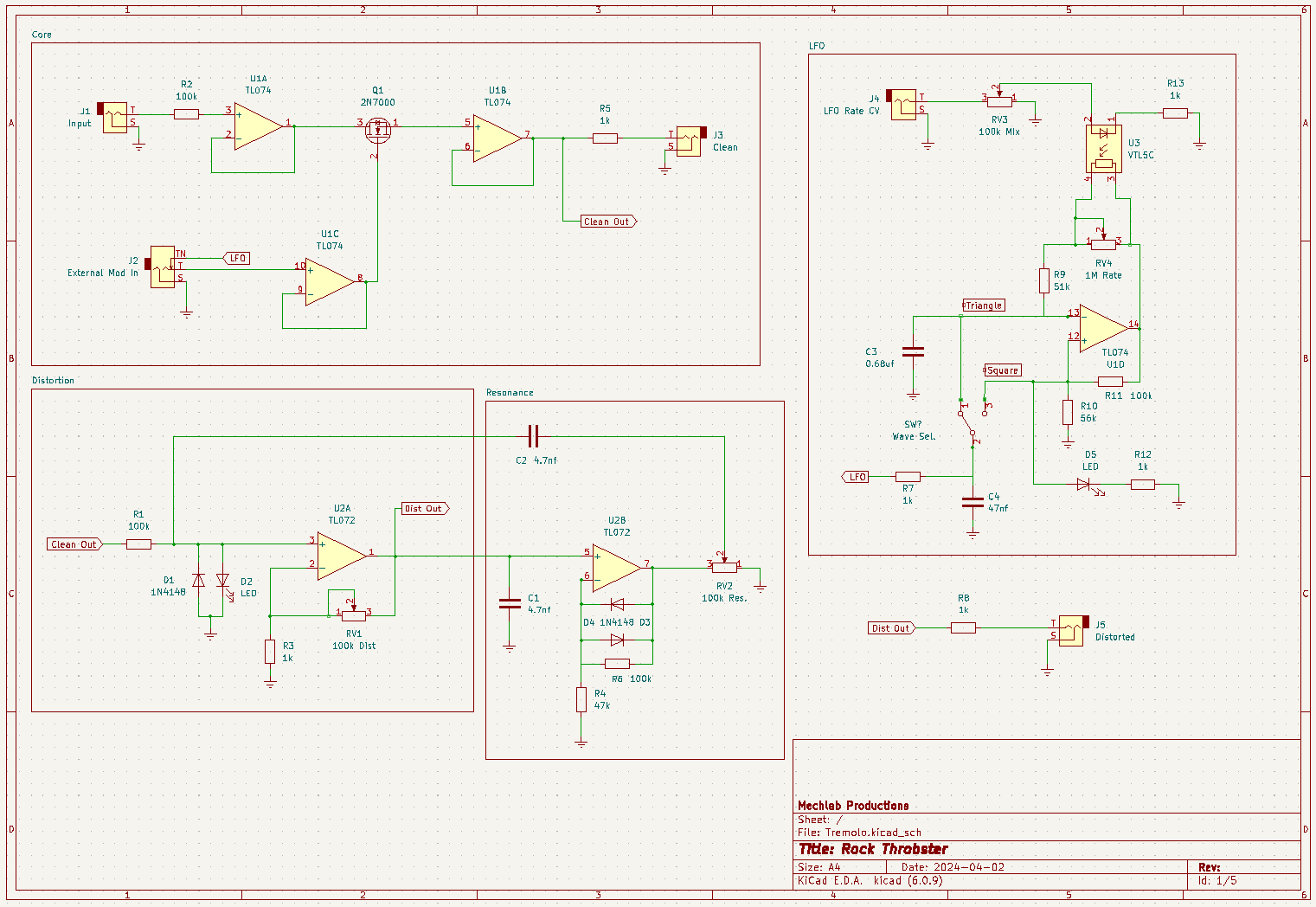
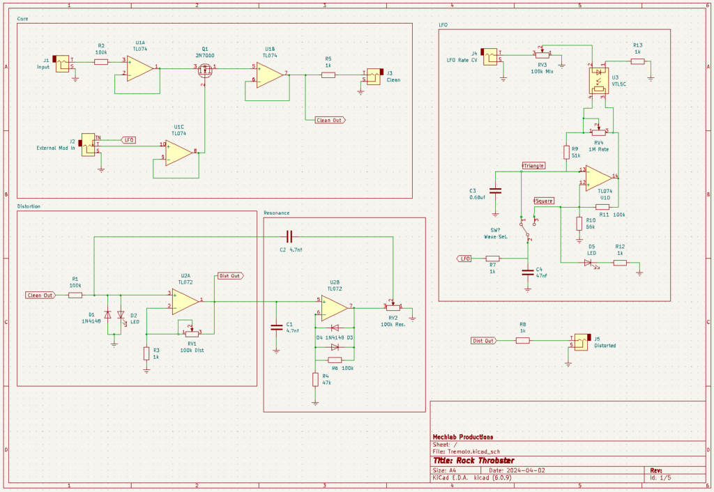
Module Core
With this understanding of the circuit, I decided to stop for the night and consider my next step. As is often the case, inspiration struck while staring at the ceiling, fighting insomnia at 3AM.
Ever since I discovered it, I’ve been mildly obsessed with adding Hagiwo’s passive MOSFET-based VCA onto everything I build. But, being that it’s a passive, single-component VCA, it’s not always great at completely shutting off the signal during periods of low voltage. However, this does make it an interesting candidate for amplitude modulation of the type I’m hoping to achieve for a tremolo.
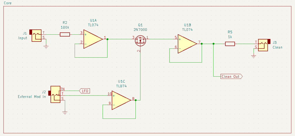
I’m using some Eurorack “standards” (in quotes because these are only loosely followed across manufacturers) on the inputs and outputs. My understanding of impedance is rudimentary, but 100k resistors on the inputs and 1k resistors on the outputs seem to be fairly common practice. The op amps here are all configured as buffers, or unity gain amplifiers. “Unity gain” is a fancy way of saying “provides an amplification magnitude of 1” or “whatever voltage you apply to the + pin, you get at the output”. This is also an impedance thing, and they might not be necessary for this circuit, but I do find that they help stabilize performance in my wonky, homemade synth, so I try to use them whenever I can. This is a great area for experimentation, though. You might find that they add nothing to your circuit and you can safely remove them to save parts and space.
The External Mod jack is a switching audio jack (I use the popular Thonkiconn jacks). A mono switching jack will have three pins: one that connects to ground (in the schematic it’s labeled S for sleeve); one that transmits the signal between the cable plugged into the jack and the rest of the circuit (labeled T for tip); and one that allows you to connect a second signal to the jack (labeled TN for … I’m not sure … Tennessee?*). If nothing is plugged into the jack, the signal wired to TN will pass through to T (and thereby, the rest of the circuit). This is called being “normalled” to that jack. In our circuit, the LFO is “normalled” to the External Mod jack, meaning that the LFO will modulate the audio through the 2N7000, unless something is plugged into the jack to break that connection. When you plug something into the jack, whatever signal you’ve plugged in will modulate the audio instead of the LFO.
If you felt like you’d never want to use an external modulation source, you could eliminate this jack and instead of normalling the LFO signal to the jack, connect it directly to the noninverting input of the op amp (pin 10). Or, skip that buffer altogether and connect the output of the LFO straight to pin 2 of the 2N7000.
Now, I just need an LFO to provide that modulating signal.
*Editor’s note: I’m pretty sure “TN” stands for “tip, normalled”
Modulation
After sorting out how the core would work, I needed a modulation source. For this, I am (once again) borrowing from Synthnerd’s Relaxation LFO–one of the simplest all-analog LFO circuits I’ve found. A nice modification here would be to use an LFO design that can sync the rate to an external clock, but the low parts count and square/triangle wave output made the Relaxation LFO an obvious choice for me.
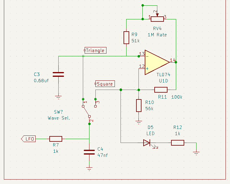
I’ve made a few minor tweaks to the LFO circuit including an LED, driven by the square wave output, to visually monitor the LFO rate. I’ve also swapped out the 2.2uf capacitor at the inverting input (pin 13 of the op amp) with a 0.68uf capacitor. The higher value capacitor takes longer to cycle, which allows for lower frequency oscillations. This is great for long, evolving modulations in a melody, but somewhat pointless for a tremolo effect. I’ve opted for a smaller capacitor that strikes a good balance between “too fast to hear” and “too slow to matter”.
Additionally, I’ve eliminated the buffering output op amp from the original design, since the LFO output is normalled to a jack that is already going through a buffer. Finally, I’ve added a 47nf capacitor to ground at the output. I found that the square wave was too square for the 2N7000 and I was getting harsh, undesirable clicks at the leading and trailing edges of the waveform. The capacitor to ground helps to smooth some of that out. I think it has something to do with shunting some of the signal to ground, but having to fill up the capacitor first. The time it takes to fill up the capacitor makes the square slightly trapezoidal. Or something. The small value of the capacitor allows the square wave to retain enough of its “edginess” without the clicking.
Most of this part of the schematic is required for the LFO to oscillate, but you could eliminate the LED and R12 1k resistor. You could also discard the SPST switch and either choose one waveform as your dedicated modulator, or you could send both waveforms (through 1k resistors) to individual output jacks. If you chose to do that, it is not necessary to normalled the LFO to the External Modulation jack. (Benefits of this approach include using the module as both a tremolo, by patching one output back into the module, and an LFO, by patching the other output into another module. You could patch the triangle into the External Modulation jack to power the tremolo and use the square as a clock signal, effectively synchronizing the tremolo to a clock.)
With this, we have a very basic, but surprisingly functional, tremolo circuit. The square and triangle waves provide distinctly different tremolo flavors and the 2N7000 handles modulation well into the audio range (which is something I couldn’t say about the vactrol circuit I started with). And the external modulation input gives it some flexibility to provide AM effects outside of tremolo. You could stop here and combine the two snippets above for a functional module. But, I wanted to push a little further to see what else I could add.
CV Over Rate
Looking at the design, one of the simpler additions to make would be some CV control over the rate. A relatively easy way to accomplish this with minimal parts is … wait for it … vactrols! Which is good, because, as it turns out, I had some vactrols to use.
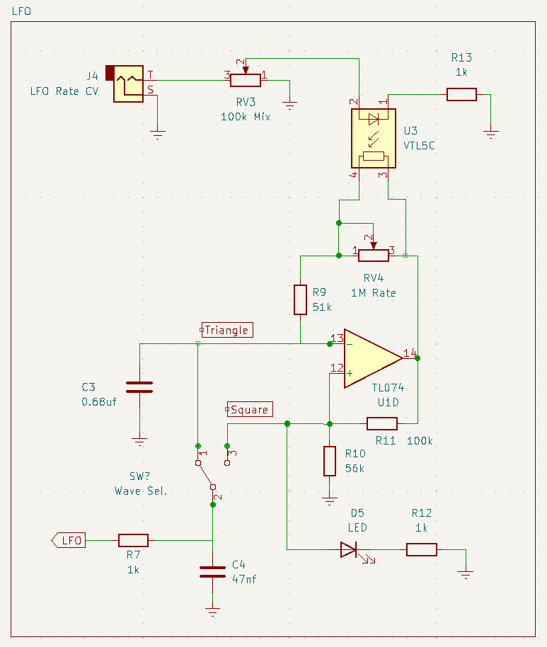
Implementation is pretty straightforward. The LDR side of the vactrol connects to pins 1 and 3 of the rate potentiometer. The anode of the LED (longer of the two legs) gets its voltage from an external CV source. I’ve added an attenuating 100k potentiometer between the CV jack and the LED. This is so I can tweak the intensity of the voltage if the CV is causing too great an effect. If you have dedicated attenuators in your synth, you can skip this pot and patch your CV through those instead. The cathode of the LED (shorter leg) needs a limiting resistor between it and ground, to keep the LED from burning out–1k works fine for my vactrols, but you might find that you get better results with higher or lower values.
This was getting me closer to a module I’d be willing to promote from breadboard to protoboard. But, I felt like there was an opportunity here to go further. I’m a big fan of noisy music and a big fan of those old psychedelic guitarists who put modulation pedals after their distortion pedals. So, why not add some distortion to the tremolo?
Clipping Diode Overdrive
For distortion, my first thought went to the clipping diode output that Moritz Klein implemented in his mixer. This is a low cost way to overdrive a signal to add a little bit of dirt, without getting harsh.
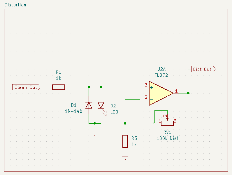
Taking the Clean Out from the core of the module, we pass it through two diodes facing opposite directions to ground. I’m sure Moritz explains why in his video (he’s great that way, but … you know … it all went over my head). He also has a 20k trimmer between the diodes and ground, but I didn’t find that it provided anything valuable, so I left it out. I chose to mix up my diodes and use one 1N4148 and one LED. This is a good area to experiment with the diodes you have on hand to see which provide the results you like best. Though the soft clipping was great, it didn’t feel like it quite enough for me, so…
Another way to get distortion in a circuit is to drive the op amp up outrageously high, smashing the signal. To do that here, I’ve gone for a 101x gain (which, of course, is physically limited by the power rails of the op amp), to crank the input signal up as high as it can go. I loved the outcome, but wanted some flexibility in usage and added a 100k potentiometer in the feedback path of the op amp to control the distortion amount. You can use the gain calculator linked above to play around with these values to come up with your desired level of distortion.
If you only want the soft clipping, replace R3 in the above schematic with a 27k resistor and RV1 with a fixed-value 100k resistor. I’ve opted for a separate distortion output, which was a simpler implementation than mixing the distorted tremolo and clean tremolo signals through a pot or crossfader.
Resonant Distortion
When breadboarding and experimenting with the distortion, I happened to grab a TL072 dual op amp, instead of a TL071 single op amp. This left me with an open op amp that I could use. Pondering my options, I began to wonder if I could lift the resonance circuit out of a voltage controlled filter schematic and drop it into my distortion to create a resonant distortion. I’ve never seen anything quite like this anywhere and I wasn’t sure it would work.
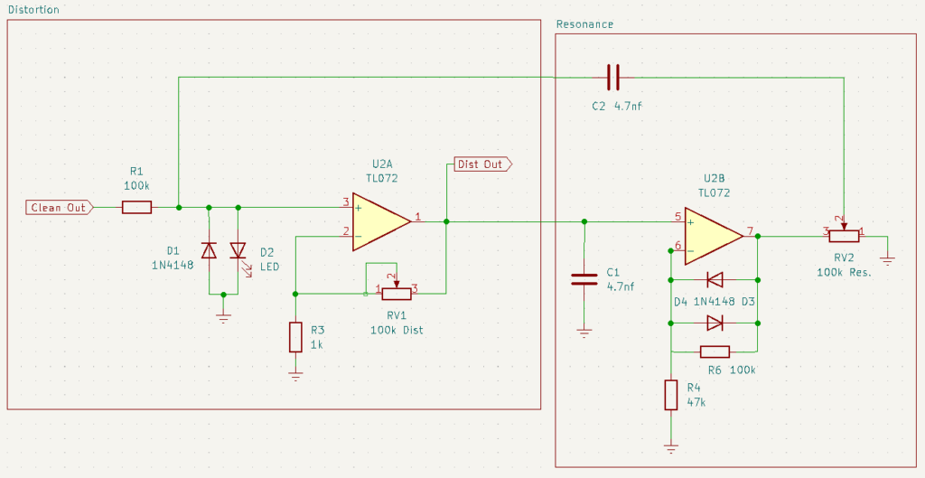
I honestly don’t understand how this works, but it works better than I could have hoped. The only drawback is that it works best at lower distortion levels. This is to be expected, though, as resonance requires enough headroom for one frequency to peak above the others. As the distortion increases, headroom decreases, leaving less space for the resonance. Once the distortion is high enough to lose the resonance peak, the resonance knob becomes more like a tone knob, affecting the brightness of the sound.
All of the components in the Resonance box of the schematic are required for the resonance, however you could cut all of this out of the schematic and everything else would still work as expected.
And So…
That’s a functional breakdown of the Rock Throbster, with some ideas of how you might adapt the circuit for your own tastes or needs. If you find this post helpful, and would like to see a functional breakdown of one of our other modules, leave a comment and let us know.
Leave a Reply