Bending Guide
Using This Guide
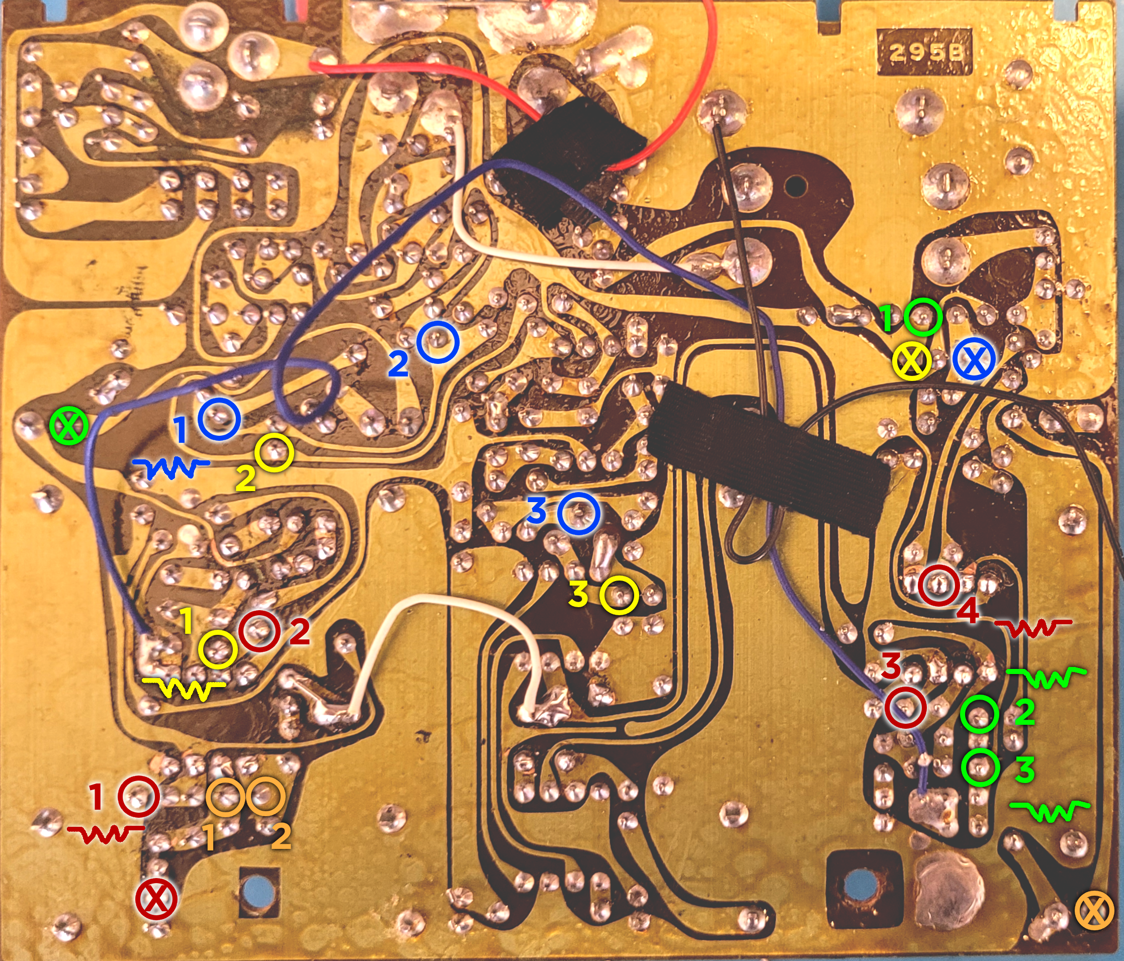
Bending Guides show specific bends that I have identified as interesting. Color-coded circles indicate separate bending points that all connect to a common point. I call this the Point of Origin (or POO) and indicate the POO with a circle marked with an “X”.
Occasionally a circle will be marked with a zigzag line . This means that I found it useful to add a potentiometer between this point and the POO. These are optional additions–the bend will function just fine with a normal switch.
Suggested Pot Values
- Red 1 – 10k
- Red 4 – 1k
- Yellow 1 – 10k
- Blue 1 – 2k
- Green 2 – 10k
- Green 3 – 20k
I appreciate that this is an obnoxious variety of potentiometer values, but these are the values I found gave me the best performance for each bend. If you don’t want to buy a bunch of new pots, just use what you have.
Additional Modifications
I also performed a few mods that I felt were outside my definition of circuit bending, but wanted to share as part of my build.
LED Indicator
In the original design, the LED indicator turns on only when you slide the power switch to the “Battery Check” position. I found this to be relatively pointless and wanted the LED to indicate when the unit was powered on.
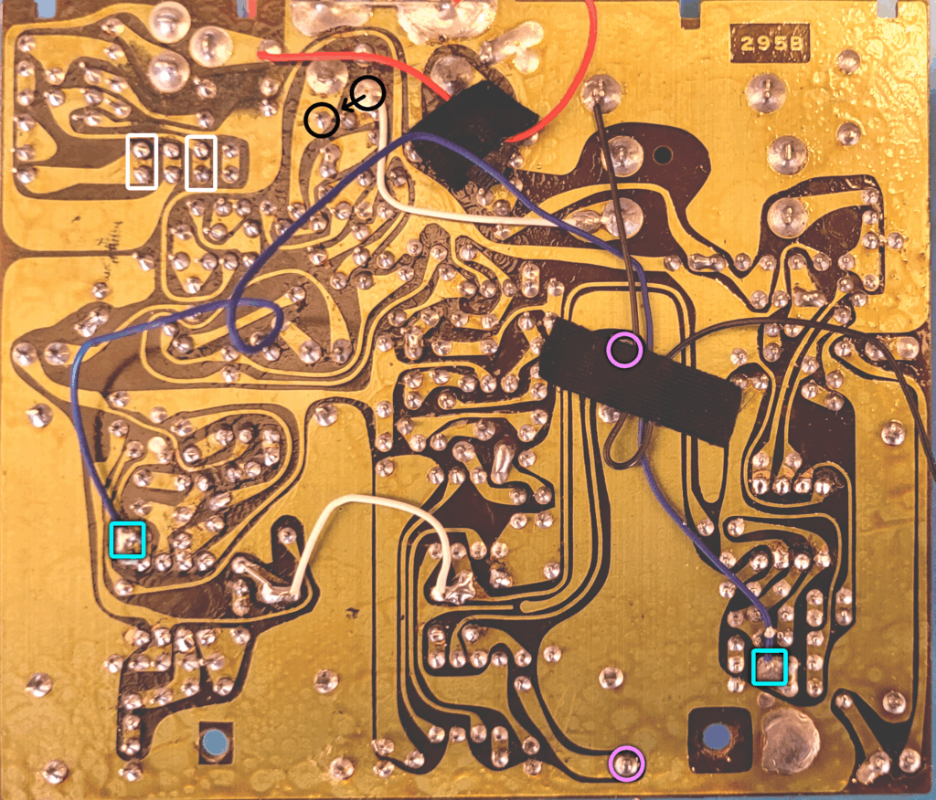
The white boxes in the guide above mark the underside of the switch. The box on the left connects to the LED. The box on the right is the On position. Connect a jumper wire between these points. (Each box contains two solder points. Both points connect to the same position of the switch, so solder the jumper to either point in both boxes.)
Delay Rate CV
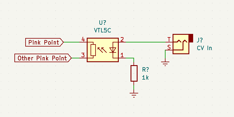
The pink points indicate terminals on the Delay slider. I thought it would be neat to control the delay rate with an external CV source, so I wired these points to a vactrol.
Mic Out Level
Since it’s no longer the 80s, I don’t have a pile of RCA cables laying around. So, I wanted to use the 1/4″ Mic Out instead. However, the Mic Out level was considerably lower in volume than the Line Out level.
There’s a factory-installed white jumper wire in the guide above that connects the Line Out to the Mic Out, through a voltage divider. I moved one end of the jumper wire from the black circle it’s in to the other black circle. This bypasses the voltage divider and results in full volume at the Mic Out jack.
My goal was only to avoid having to buy RCA-to-1/4″ adapters, but the bonus outcome is that the Microphone slider now becomes a beautiful distortion level control.
Mix Options
There’s no true wet/dry mix on this device. The Depth slider controls the wet signal level, but no true mix option. The light blue boxes indicate the ends of a factory-installed blue jumper wire. This wire connects the dry signal to the output op amp.
I tried replacing this with a pot for true wet/dry mixing, but found the results underwhelming. Due to the design of the op amp stage, the dry signal wasn’t audible for most of the range of the pot, making it impossible to achieve any meaningful mixing.
Instead, I opted for an On-Off-On (aka Center off) SPDT toggle, which gives me the option of: Standard mix, Wet only and Reduced dry mix.
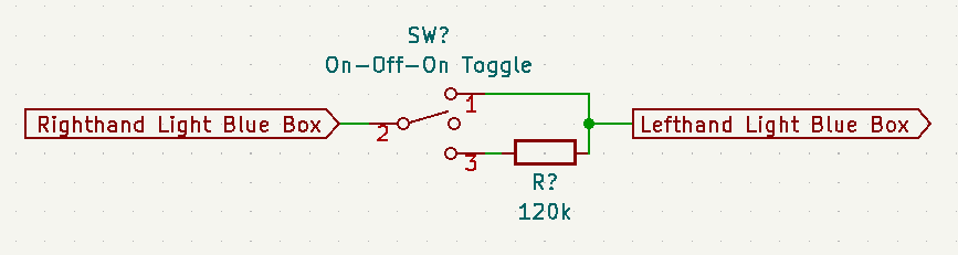
Tinker with the value of resistor to get the reduced dry mix of your liking. I found that values greater than 120k attenuated the signal too much. When the wet signal was more prominent, it started to sound like two signals playing out of sync, rather than the mixed signal I was looking for.
(Feel free to use this as an example of when mixed signals are desirable.)
MN3207 Replacement
This device uses an older MN3207 BBD (“bucket brigade delay”) chip to create the delayed sound. The MN3207 has a maximum delay time of 51.2 milliseconds. I swapped this out with a CoolAudio V3208, which has delay times up to 102.4 milliseconds.
With longer delay times, you will start to hear a noticeable clock noise whine. I might revisit this in the future and add a passive lowpass filter to the output to tame some of the noise.
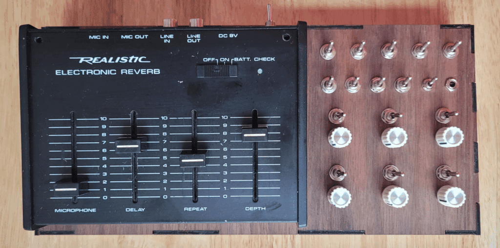
Built from: Radio Shack Realistic Reverb
Number of bends: 10 15
Description: Outfitted with 10 bends that create crushing walls of feedback and tone generation, the Unrealistic Reverb can be used as a noise generator in its own right.
**New!**
This was not part of my original plan for revisiting old bends in 2025, but I received a few questions about the old bending guide and thought it was worth re-exploring.
As the result of a dodgy eBay transaction, I ended up with a nonfunctioning unit. After some patient probing and parts-replacing, I was able to get it up-and-running again, but I’m not entirely sure it’s 100% right.
Because I’m not confident the unit was at 100% when I started, I offer this guide with the caveat that your results might be different from mine.
(Which should be a standard caveat for all bending projects.)
All of that said, I’ve really found some charming bends here. Many of my original bending points were still useful and valid, but I’ve found a few more to pad the total out to 15. Various walls of delay feedback. A few subtle timing bends. Top it all off with some sublime distortion and the result is a really fun slapback delay unit.
I’ve also documented some more traditional modifications that I felt added more value to the project. Specifically the Mic Out Level mod, which opens up a whole world of beautifully warm and creamy overdrive.
Demos
The following demos all feature a drum machine running through the Unrealistic Reverb. Each demo starts with a clean signal, then the delay Depth is turned all the way up, then the bend is connected. There is slight compression and limiting on the signal, but no additional effects.
Red 1
Red 2
Red 3
Red 4
Blue 1
Blue 2
Blue 3
Green 1
Green 2
Green 3
Yellow 1
Yellow 2
Yellow 3
Orange 1
Orange 2
Delay Rate CV
Did you build this? Let us know in the comments below!
4 responses to “Unrealistic Reverb”
-
Wow – this is obnoxiously amazing! Thanks for sharing all your hard work – I wondered if you thought it would be possible to accommodate all of these mods into the original casing or do you think it requires al external housing like you’ve undertaken? Brilliant site – thanks again!
-
Thanks! The first time I bent one of these, I didn’t use an external enclosure–I installed toggle switches along the sides. I think you could find enough room in the original housing to use sub-mini toggle switches and squeeze in all the bends and mods. You might struggle to find room for the pots and the CV input, but those are really optional. Good luck!
-
-
Hi, This is great and thanks for doing this. I had one of these back in the mid 1980’s and i remember it doing far more that what it did when I bought the un-modded unit recently. was disappointed but then I remembered seeing your bends a while back, so I looked it up but what io found wasn’t what i remembered seeing.
I went ahead and did a bunch of the bends, mainly the color coded red, yellow, blue, green and orange. I also did the white boxes from the additional modifications image- and the mic level jumper.
I seem to remember, but I could be mistaken, that there was a description of what the color code did etc, but I haven’t been able to find it on the internet. I’d like to to label what the knobs and switches do and was hoping you could point me in the direction to find itIts pretty amazing what it does now. Planning on doing more of the mods when I get a chance and possibly turn it into some type of synth.
Thanks in advance
-
We did recently update this guide with some new information. The previous guide dated back nearly 20 years, so that might be what you remember seeing previously.
Glad to hear that the project turned out well and sounds amazing! We’re really happy with ours, as well.
As for descriptions and labelling the bends, we’re not aware of any specific descriptions. Every circuit bender has their own take on what or how to name individual effects. Our “distortion” might be your “overdrive” or “Mom’s Dry Hug” or whatever. Our recommendation is to label them in a way that makes sense to you and your use case.
And keep in mind that individual bends often take on new characteristics when used in conjunction with other bends. A specific switch might result in mild fuzz when used solo, but turn into a wash of feedback when used with another switch.
Good luck with future modifications. Let us know if you find anything we’ve missed.
-
Leave a Reply