

What happens when you mix distortion with an envelope filter? I mean… This, I guess.
Another module destined to be nominated for “Most Creative Module Name”, Envelope Distortion is just that. Very straightforward operation, plug a signal in, select the “Tone” mode, adjust the mix and enjoy the noise.
Works best when placed after an envelope-triggered VCA, but also functions as a nice, harsh distortion, even with no envelopes in the mix. Tone switch selects between two distortion effects: Harsh and Harsher.
Schematic
As with any schematic found on the internet, exercise caution when building. Test the build before plugging it into your case. If you find mistakes in the schematic, or you have recommendations for improving the design, feel free to contact me and let me know.
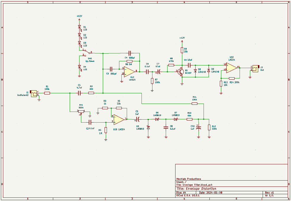
BOM
- Capacitors
- 680pf (2) – C3, C4
- 4.7nf (1) – C1
- 100nf/0.1uf (3) – C2, C6, C8
- 1uf electrolytic (2) – C5, C10
- 10uf (1) – C9
- 47uf electrolytic (1) – C7
- Resistors
- 1k (1) – R3
- 10k (1) – R13
- 20k (1) – R9
- 22k (1) – R2
- 33k (1) – R5
- 50k (1) – R10
- 100k (3) – R1, R7, R11
- 200k (1) – R14
- 330k (1) – R12
- 470k (1) – R8
- 1M (1) – R4
- 5M9 (1) – R6
- Potentiometers
- 500k Mix (1) – RV1
- ICs
- LM324 (1) – U1
- Transistors
- BC337 (1) – Q1
- Diodes
- 1N4148 (2) – D8, D9
- 1N5819 (3) – D5, D6, D7
- LEDs (4) – D1, D2, D3, D4
- Audio jacks (2) – J1, J2
- SPDT switch (1) – SW1
Design Notes
This is another older design that I’ve dredged up to share. I’m positive this is based on someone else’s circuit design (the excessive variety of resistor values tells me as much), but I am not sure whose. It was likely cobbled together from snippets of distortion circuits and envelope followers.
Because I can’t remember what inspired this, I’m at a loss for a few things:
- Why an LM324 instead of a TL074? It’s not an op amp I typically keep on hand. It’s also not a rail-to-rail op amp, so I don’t think it’s important to the design. You should be able to substitute it for any general purpose op amp.
- Why a BC337? Again, not a component I tend to keep on hand, so I was likely blindly following a schematic I found elsewhere. I have a strong suspicion you could swap that out for a more common NPN transistor (2N3904, 2N2222) without any issues.
- The switch labeled “Tone” on the faceplate was originally labeled “Up/Down” in the schematic. I think that portion of the circuit was lifted from an envelope filter design and was originally designed to control whether the cutoff frequency went up or down when the filter was triggered. It doesn’t really have that effect in this circuit, which is likely why I renamed it “Tone” when I made the faceplate. That said, it’s not really a tone adjustment, either. It’s more like two different distortion modes.
Demo
Coming soon
Leave a Reply