
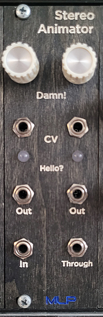
One of my least creatively-named modules to date, Stereo Animator does precisely what it says on the tin. Used to stereoize mono signals, plug something into the input and get two copies from the output. “Well, that’s not very exciting” you might think. And you’d be correct… If that’s all the module did.
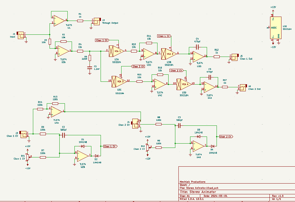
Each channel is routed through two VCAs, where the VCA output is controlled by the corresponding channel CV input. When the CV goes high, the volume for that channel goes high. When the CV goes low, the volume for that channel goes low. By plugging asynchronous LFOs into each channel, the volumes for each channel modulate independently, creating a stereo effect.
An inverted copy of CV 1 is normalled to CV 2, allowing for a faux auto-panning effect. Each CV input also has a knob to add DC offset to the signal, biasing the CV and controlling the depth of the effect, as well as gain of the output–which can be pushed into distortion territory.
Schematic
As with any schematic found on the internet, exercise caution when building. Test the build before plugging it into your case. If you find mistakes in the schematic, or you have recommendations for improving the design, feel free to contact me and let me know.
BOM
- Capacitors
- 470pf (2) – C4, C5
- 560pf (2) – C2, C3
- 1.2nf (1) – C1
- Resistors
- 220R (1) – R5
- 1k (3) – R1, R12, R17
- 10k (6) – R2, R3, R10, R11, R15, R16
- 15k (1) – R4
- 100k (6) – R6, R7, R8, R9, R13, R14
- Potentiometers
- 100k (2) – RV1, RV2
- ICs
- SSI2164 (1) – U3*
- TL071 (1) – U1
- TL074 (2) – U2, U4
- Diodes
- 1N4148 (4) – D1, D2, D3, D4
- Audio jacks (6) – J1, J2, J3, J4, J5, J6
*See the Supply Voltage note below
Design Notes
This is an odd one. I’m not sure when I built this, or why I never shared it previously. I have photographic evidence of it in my case as far back as May, 2024. But the KiCad schematic has a date stamp of January, 2026. Mysterious.
Supply Voltage
Also mysterious is that the schematic shows the SSI2164 being powered by a bipolar 12V supply, which is outside the operating specifications in the datasheet. At least, I think it is. The supply voltage range for the SSI2164 is listed as +/-18V. I read this as a total voltage swing of 18V, relative to ground. For a symmetrical supply, that would be +9V and -9V.
That said, I’m almost positive I used the AS2164 and not the SSI2164, since the AS2164 comes in a through-hole DIP package. The datasheet for the AS2164 has the supply voltage listed as +18V,-18V–which is much less ambiguous. And also a very different range. Not sure if I’m reading the SSI datasheet wrong, or they printed it wrong, or there’s a functional difference between the two.
I have the symbols for the SSI product line in KiCad, which I would have used out of laziness expediency instead of trying to hunt down the AS version. I could have relabeled the symbol in KiCad, but honestly, I’m only just now catching it and not feeling motivated to make the correction. Sue me.
Did it take me longer to write this out than it would have taken to correct the schematic? Shut up. No one asked you.
Moving On
Not much to explain with this one. There are ways to break this down and simplify a build, but it would sacrifice enough functionality that I’m not sure there’s benefit.
It stands to reason that a version of this design could be made using OTAs (e.g., LM13700), but all the op amp stages would need to be adjusted to account for the finnicky current needs of an OTA. As designed, the CV input would almost assuredly fry an LM13700.
Demo
Coming soon
Leave a Reply