Bending Guide


Built from: Yamaha PSS-140
Number of bends: 8
BentPedals.com Description: With the Glitch Machine, disrupt the flow of data between the main IC and the FM chip where the sound data is stored. The result is a bizarre and uncontrollable mixture of sounds: From luscious pads to absolutely devastating noise. In addition to the sounds it can mangle… it also mangles the 10 preset drum beats and the demonstration song creating some of the glitchiest drum beats you’ll ever hear.
This bending guide is different from other guides on this site. The Glitch Machine build was an extension of the PSS-270 tutorial provided by Kevin Rees. For more information, I’ve included the original tutorial, as salvaged from Archive.org’s Wayback Machine. This tutorial provides the context necessary to use the bending guide images.
In my images, the red and blue dots correspond to the main and FM chips (as they do in the tutorial below), and the yellow dots correspond to the jumpers that need to be cut or desoldered (represented by green dots in the tutorial below).
The Kevin Rees tutorial:
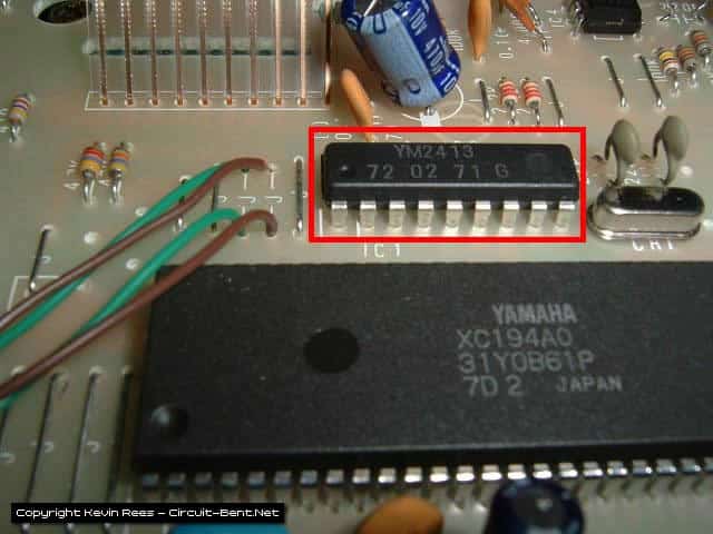
This bend involves cutting data lines that go from the FM synth chip (YM2413) to the main chip (XC194A0). The pins on the FM chip that go to the main chip are pins 2, 3, 4, 5, 6, 7, 17, and 18. You cut the traces, and then solder wires on either side of the cut. Take the pair of wires from one cut, and solder them to a switch, and this will allow you to turn the flow of data on and off.


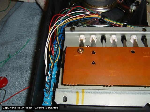
The green dots indicate four solder points that are for two jumpers. These jumpers make the connection for pins 17 and 18. I de-soldered them and put wires through to make the connections for pin 17 and 18. The black line is where you *carefully* cut the data lines. I used a volt meter to check and make sure that the lines no longer had continuity.

Some people recommend drilling very small holes on both sides of the trace cuts, and putting wires through them, or scraping the coating off so you can solder on it. I just soldered the wires onto the pins of the chip, which can be dangerous because you run the risk of overheating it. I used a pair of wires that are the same color for each connection to make wiring up the switches easier.

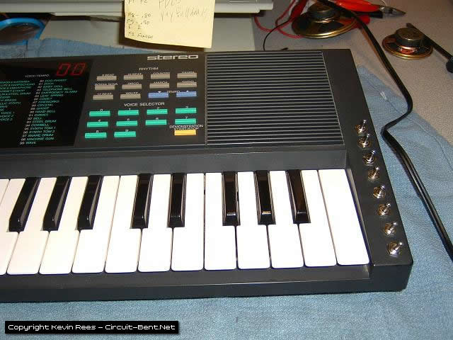
I found the most room for the 8 switches on the right side of the keyboard. Just measure and drill carefully, and it will come out looking great.
What the Bends do:
Each switch now controls the flow of data from the FM chip to the main chip. Turn the PSS on and select a patch (let’s pull up #89 “ghost”), I usually play some keys(don’t know if you have to do this or not), then turn some switches off , now select a different patch, and turn the switches back on. Now try playing the new patch. If it went well some of the data from the all patch got held up, and then inserted into the new patch making a totally different sound. Sometimes leaving the connections off will change the sounds also. I’ve noticed them some of the bent up patches will only work when multiple keys are played. I’ve heard that this will effect the drums as well, but I haven’t gotten it to do much with them as of yet.
Getting some good sounds out of this takes some tinkering, but it’s worth it. The only downer is that it’s hard to reproduce the sounds that you get, so if you have a good one be sure to grab a sample while you can. Using the keyboard this way can corrupt the data to the point where the chip crashes in a noisy mess, but all you have to do is turn all the data connections back on, and turn the keyboard off, then back on. All the data connection switches have to be on for the keyboard to work “normally”.
Did you build this? Let us know in the comments below!
Leave a Reply