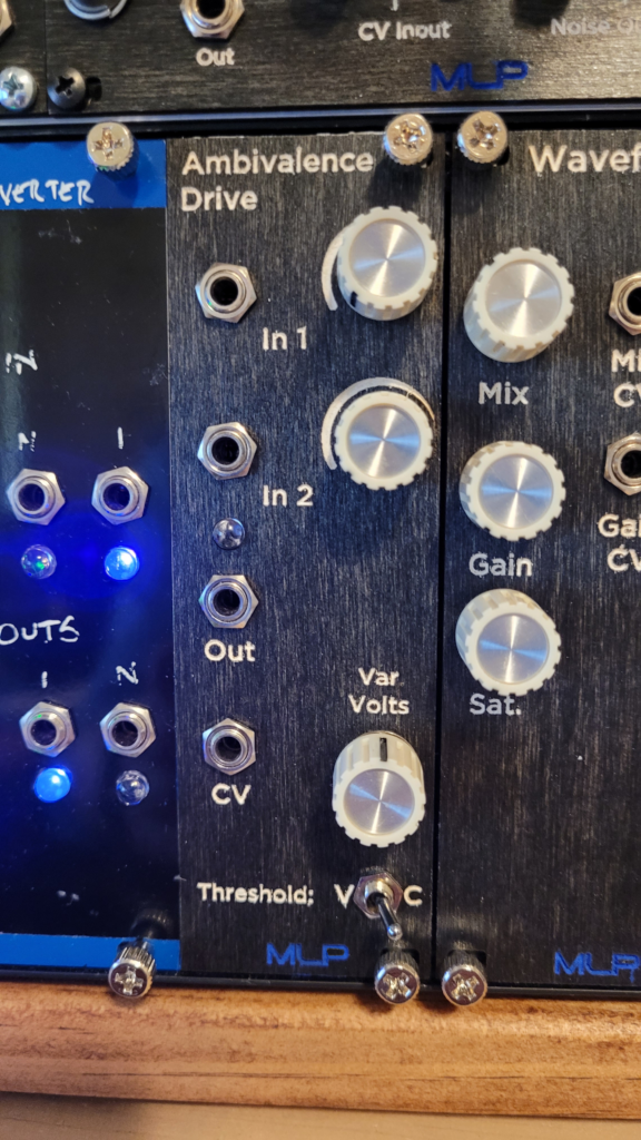
Make up your mind, already. Ambivalence Drive is here to help. Built around a DG419 analog switch, Ambivalence Drive uses control voltage to switch between two input signals, routing to a single output.
Use the toggle to choose between a constant 5v reference or a variable voltage set with the Voltage Range knob. The constant reference can be used to control the switch with a gate/trigger/clock signal. Whereas the variable voltage knob can dial in a specific voltage reference, allowing for things such as using the CV from a sequencer or S&H to switch between oscillators when the note is above a certain frequency.
Patch another audio source into the CV input and the Ambivalence Drive functions just like the Thunderdome.
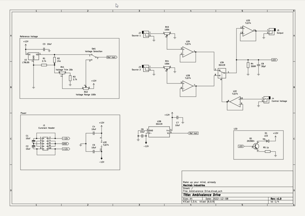
Schematic
As with any schematic found on the internet, exercise caution when building. Test the build before plugging it into your case. If you find mistakes in the schematic, or you have recommendations for improving the design, feel free to contact me and let me know.
BOM
- Capacitors
- 30pf ceramic capacitor (1) C8
- 10uf ceramic capacitor (5) C3, C4, C5, C6, C7
- 10uf electrolytic capacitor (2) C1, C2
- Resistors
- 300R resistor (1) R4
- 1k resistor (1) R5
- 2.7k resistor (2) R1, R3
- 24k resistor (1) R2
- Potentiometers
- 20k single-turn trimmer (1) R1
- A100k (2) RV3, RV4
- B100k (1) RV2
- Transistors
- 2n3904 transistor (1) Q1
- ICs
- TL074 op amp (1) U2
- DG419 analog switch (1) U3
- L78L05 5v regulator (1) U1
- LED (1) D1
- Eurorack power header (1) J1
- Audio jacks (4) J2, J3, J4, J5
- SPDT toggle (1) SW1
Calibration Notes
The 20k trim pot in the Reference Voltage section is used to set a minimum voltage threshold. The switch requires some level of voltage at the reference pin, otherwise it will never trigger. To calibrate, turn the Voltage Range knob fully counterclockwise and adjust the Voltage Trim until the Ref Volt output is 0.5v
Demo
Did you build this? Let us know in the comments below!
Leave a Reply